The parts:
- 1 Arduino nano
- 1 5v solenoid
- 1 4 digit 7 segment display
- 1 logic level mosfet (I used a TIP122G instead because it was lying around but it’s not the best choice at all)
- 1 diode
- 8 330ohms resistors
- 2 270ohms resistors
- 1 100ohms resistors
- 2 push-buttons
- electrical wire
- fimo clay (or a 3d printer)
Circuit diagram:

The layout of the connections is far from ideal. I should have planned better but I recognized my mistake having already soldered half of the wires.
Afterwards, I think I should have added two components a switch to turn the arduino on and off and a buzzer to signify the end of the timer.
A pdf version is available here.
The code
The repository is here.
The code is written in C++ : I like to use classes, it keeps things all clean and readable. We are using 5 classes for this application:
- Timer : handles the timer mechanism. Uses the internal clock of the arduino to keep track of the elapsing time.
- Lock : deals with the solenoid by controlling the transistor. Can be either open or closed.
- Button : state can be interrogated ; either held, pushed or released.
- Display : controls the segment display. Used through its show() method which accepts any int between [0, 9999].
- PinRegistry : where all the pin numbers are declared.
Soldering the components
We start by soldering the pins headers of the arduino nano.


Testing and preparing the components :


Soldering the resistors to the display connections :


Meet the Arduinoctopus


Soldering the connections to the display :


Yay nothing burned yet !
Preparing the box
We need to cut a hole on top of the box in order to embed the display + the 2 buttons


Ok it is not that straight…but since the box will be painted in black it should be ok (yeah I told myself that…). About that, let’s paint the box !


Making the lock :
Since I don’t have a 3d printer, I used some fimo clay which was easy to re-model and glue. It does the job pretty well.

We need to make a little triangular piece on which the solenoid will slide when the box is being closed. The solenoid will then relax itself under this piece, thus preventing the box from opening.


We also need an L-shaped part to serve as a base for the solenoid.
Now to embed the circuit, tweak a few parameters and we’ll be all set !


The result

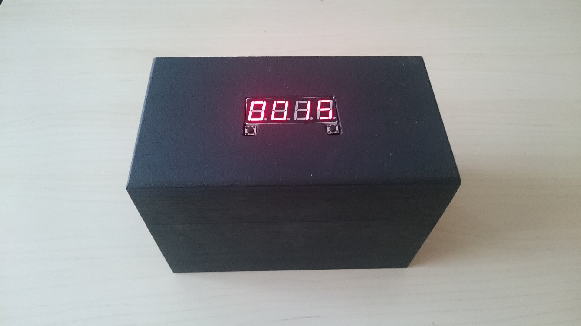
You can find a quick video of the box in action here.
I hope that you enjoyed this project and that it gave you some ideas in return. Please drop me a line if you want any explanation/if you have any critic or for a new tutorial idea !
Hello! We are teacher students and we are trying to build the savebox you’ve made. But we need your help! Can you tell us how we can download the codes to arduino library? We can’t find the right file. When we are trying to download the code, it keeps saving them in html. instead of cpp or h. Hope I made my problem clear.