The backstory
A few weeks ago I published a post explaining how to make what I called an “Anti-procrastination box”. Shortly after I received the following message :
Hey!
I’m a big fan of the anti-procrastination box you’ve built.
I’m a web developer and have actually been looking for someone I could hire to make a prototype of a product very similar to what you’ve constructed.
No need to say that I was thrilled. But then I remembered : “hey, I’m no engineer. Playing around with a breadboard is one thing, making a commercial-looking prototype quite another one!”. Fortunately I wasn’t the first amateur maker who wanted to go pro, thus a month or so later I ended up with a working prototype and 4 pages of notes summing-up informations gleaned around the web.
What I’d like to do here is to centralize this information so you don’t have to go through pages and pages of EEVblog forums or obscure sub-reddit as I did in order to find what you are looking for.
By no means is it the essential guide to prototyping or anything like that. As I told you I’m an amateur doing its best, so if you’re better advised than I am and find that something that I wrote is wrong or that you would like to add something, drop me a line and I’ll correct it/add it right away.
Our dummy-prototype : the MoodCube
As a pedagogic support, we are going to develop a very simple prototype together. I’m a strong believer in the virtues of learning by example. Together we will design a circuit so that we can have PCBs made specifically for our product. Then we will design the enclosure and generate clean stl files so that it can be 3d printed.
The incredible product we just invented and that surely will make our fortune is the MoodCube. It’s a plastic cube with RGB leds embedded on 5 of the 6 faces. It is controlled by an IR remote.
From Arduino to standalone circuit
For now we have a proof of concept of the circuit consisting of one VS1838B IR receptor, an Adafruit smartpixel breadboard format, an Arduino Uno and some remote that was lying around. The code used is from Adafruit’s great tutorial about IR sensors with a few tweaks and the values fitting my remote.
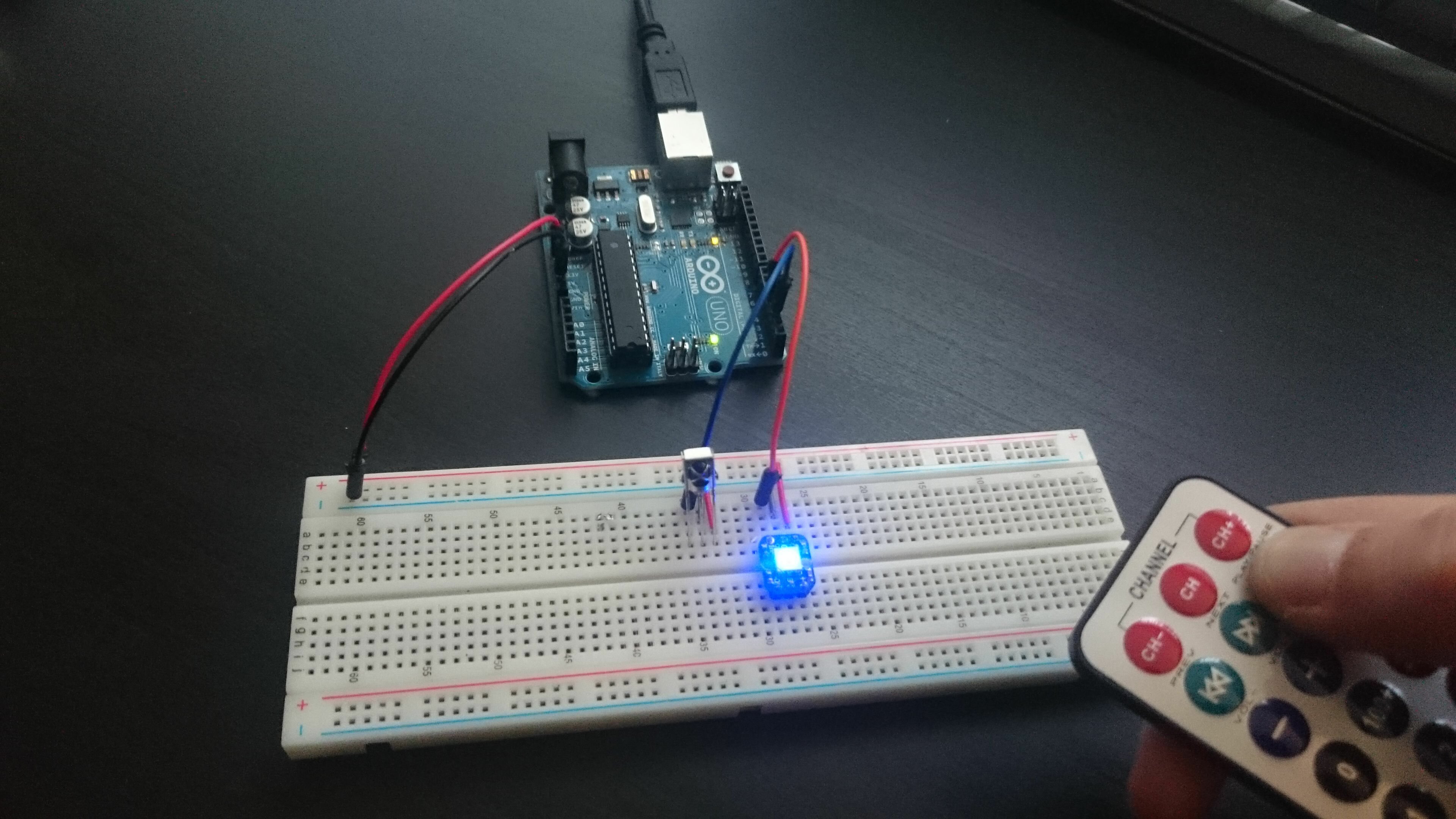
The first thing we have to figure out is : what is the simplest form of this circuit ? What are the essential components, and the ones we can get rid off.
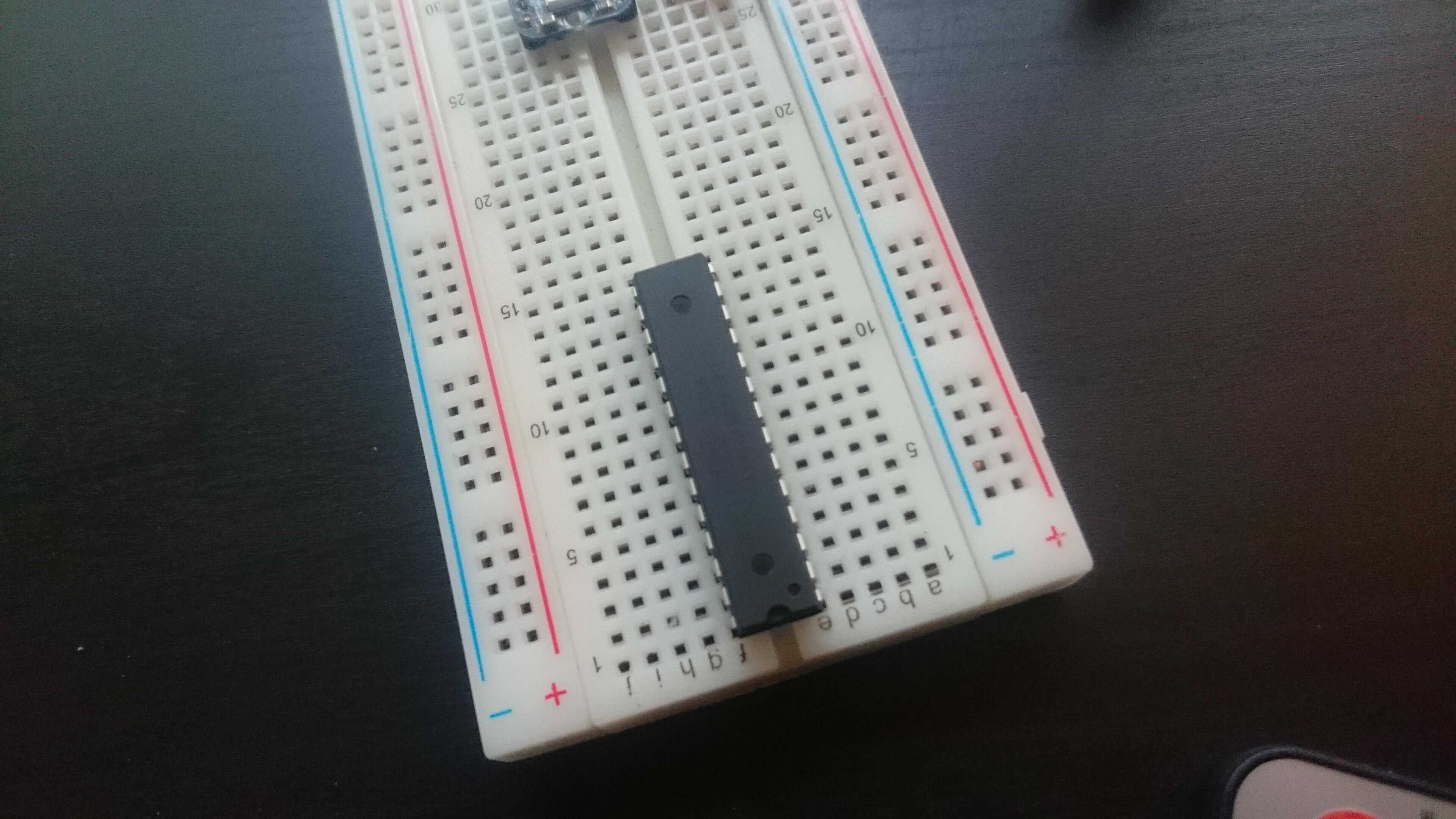
Here’s an instructable on how to make a standalone ATMega chip on breadboard that helped me. The projects section of AVRFreaks is also a great source of inspiration.
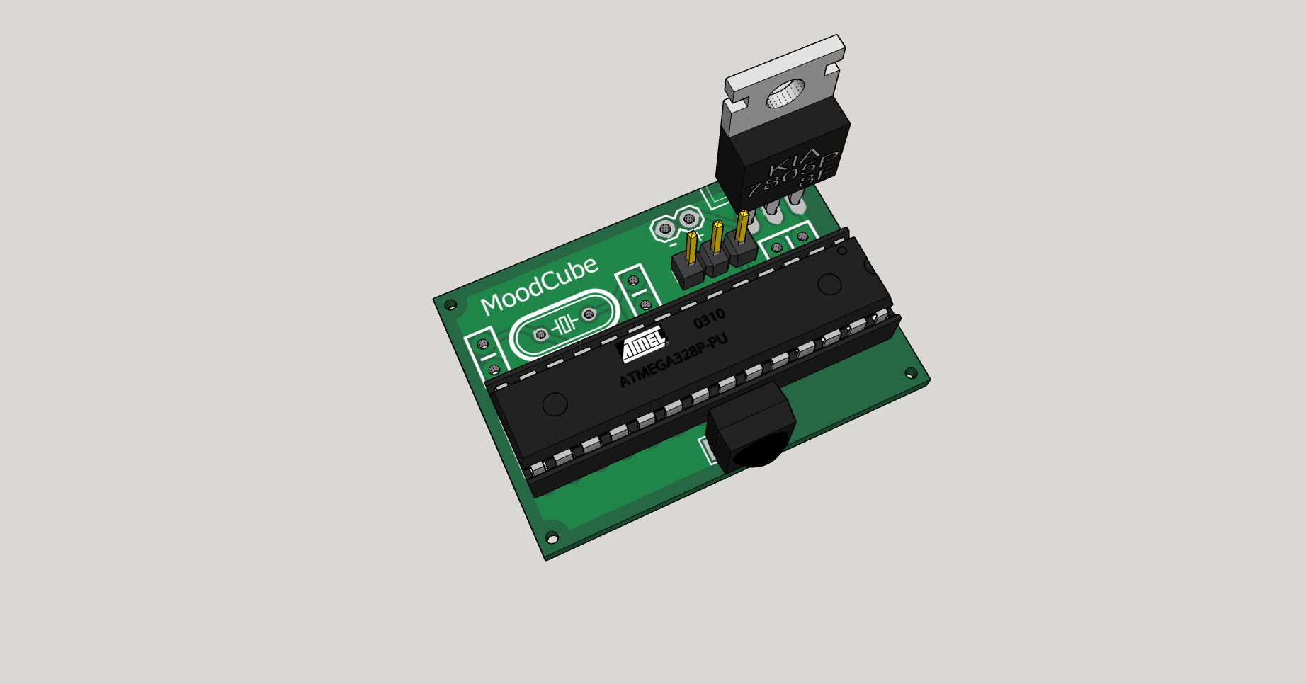
In our case, we need at least an MCU and a crystal since the IR signal decryption requires precise timing. I could (and probably should) use an ATtiny for such an application but I only had some ATMega328 in my parts bin. Add some capacitors to stabilize the circuit. What about the power ? A 9v battery will do, but we need a voltage regulator since we want the MCU to be fed only 5v (the arduino is not doing that for us anymore!). A chance I had a MCC7805CT L7800 lying around.
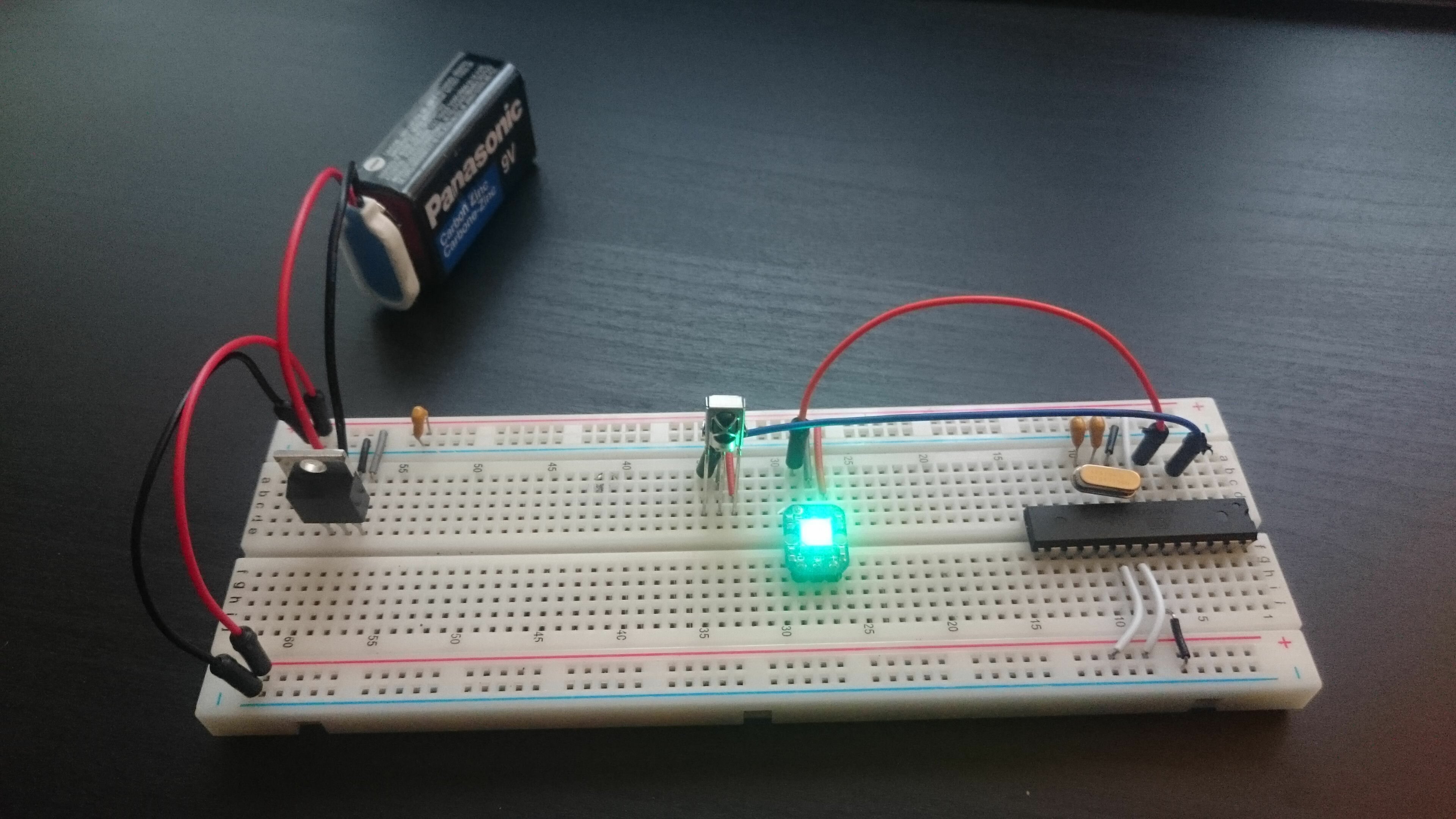
What are we doing here ? Verifying that our bare circuit works just we intend it to before moving on to designing the PCB.
PCB design and production
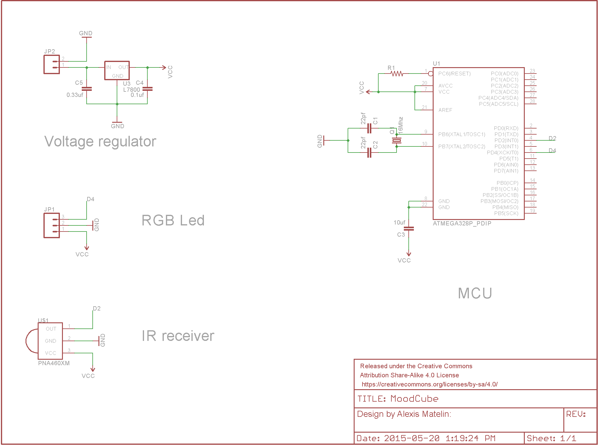
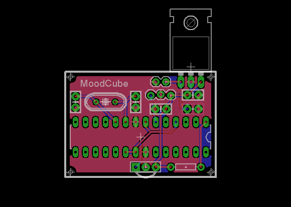
Now that we have set our minds on a specific circuit design, it’s time to make a beautiful schematic using Eagle ! Once the schematic is done, you can start to make the PCB layout itself. Sparkfun wrote a guide explaining how to complete these two steps with Eagle:
- How to make a circuit schematic.
- How to make a PCB layout.
You can find some tips about eagle here and over there is a tool allowing you to compute the optimal trace width according to your circuit specifications.
The question you ought to ask yourself at this point is : what are the requirements that will shape your circuit ? Do you want through holes or surface mounted components ? SMD components mean lowering the cost of assembly for high production volumes (a pick and place machine once configured will be able to make pretty much any quantity for ridiculous marginal price increase, whereas through holes components need to be places by hand in most places). On the other hand, if you don’t have a reflow oven and just want to make a few boards for yourself, you will probably prefer the through hole option. It is a also a good pick if you intend to sell or distribute your product as a kit of parts to solder.
Always keep in mind the overall design of your product too, it might influence the form-factor of your board or vice-versa.
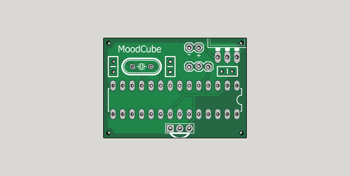
So let’s assume that we’ve answered these questions. We now have our circuit schematic and board layout! Get the files here.
The next step is to actually make the board. Will you do it yourself or have it produced ? It’s your call and it certainly depends on the requirements of your projects. You can find info about the DIY way here.
If you want to have it produced, the question will be : should I go for a local or a Chinese company ? Once again it depends on how rushed you are (local companies usually have a quick turnaround option but it comes at a price. As an example I paid 140$ca to APCircuits for 4 boards with top and bottom soldermask + top silkscreen. It arrived 5 days later and the quality of the boards was very high standard). If I had ordered them from china, I probably could have had 10 boards for 14$ delivered in 2/3 weeks. I feel like I have to mention what every professional told me when speaking about outsourcing the production to China : apparently they WILL make a copy of your plans just in case it could be sold in their own market. I have no idea how true this is, but about five different persons told me to think twice about that “fact”. (I would love to have some insight about that in the comments).
So, that being said, here is a few links :
- Ladyada PCB manufacturers list.
- PCB Shopper : price comparison website.
- OSH Park : “OSH Park is a community printed circuit board (PCB) order.” Worth to mention that they accept Eagle files on top of the usual gerbers.
- Seedstudio : a SF based company acting as an intermediary between you and Shenzen. They offer PCB prototyping, soldering and 3d printing services for a very attractive rate.
- Dirty PCBs : “No bull, just crappy PCBs” from China.
Apart from the PCB, you will need a solder stencil if your components are surface mounted. The stencil is used to apply the solder paste on your circuit. The components are then placed (manually or with a pick and place machine) on your board and it goes in the oven where the past melts on the pads of your components. As always, you will have to make a tradoff between the quality of your stencil and the price you are willing to pay. You can get a thin laser-cut plastic one from OSH stencil for 10$ a piece or a stainless steel version for 125$.
Seems like the PCB part of our project is taken care of so what now ? Let’s start to design the enclosure!
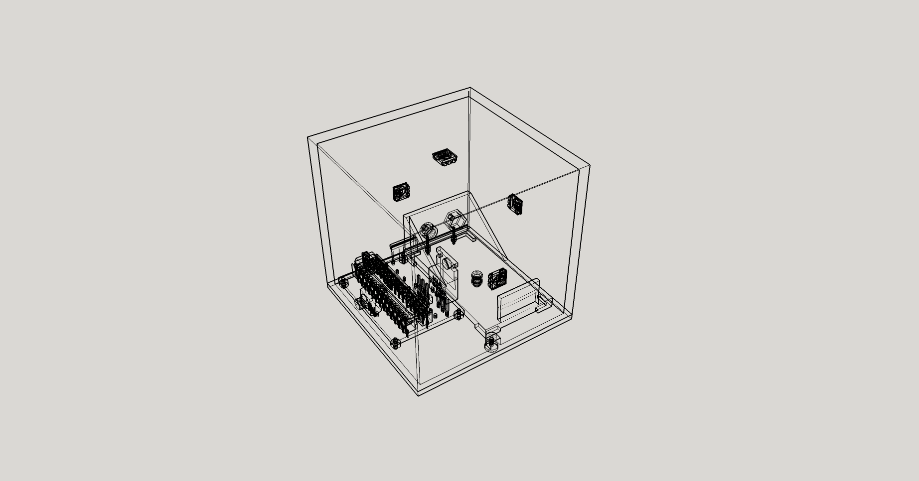
Enclosure design and 3d printing
We will use Sketchup to help us with the CAD job and Meshlab to verify the integrity of the .stl files generated.
First export a model of your PCB from Eagle so that we can design around it using a very convenient extension : Eagle Up. Browse Sketchup’s 3d warehouse in order to find components to fill the board (if you want to of course). Very often the scale is in meters and you’ll have to scale everything down (this is because Sketchup was made for architecture modelling purposes so it’s not optimized for sub-meter precision. Thus it’s common to design in meters and at the end scale down to the real size).
Then you can start to design your enclosure. Here are some resources that helped me :
- Youtube video explaining how to use Sketchup for 3d printing.
- Building an enclosure using Sketchup.
- How to check if a model is water tight.
- Various tips and tricks and some helpful guidance regarding the move tool in sketchup (this thing can get you mad if you don’t know how to use it properly, trust me…).
- Where to find textures for your models.
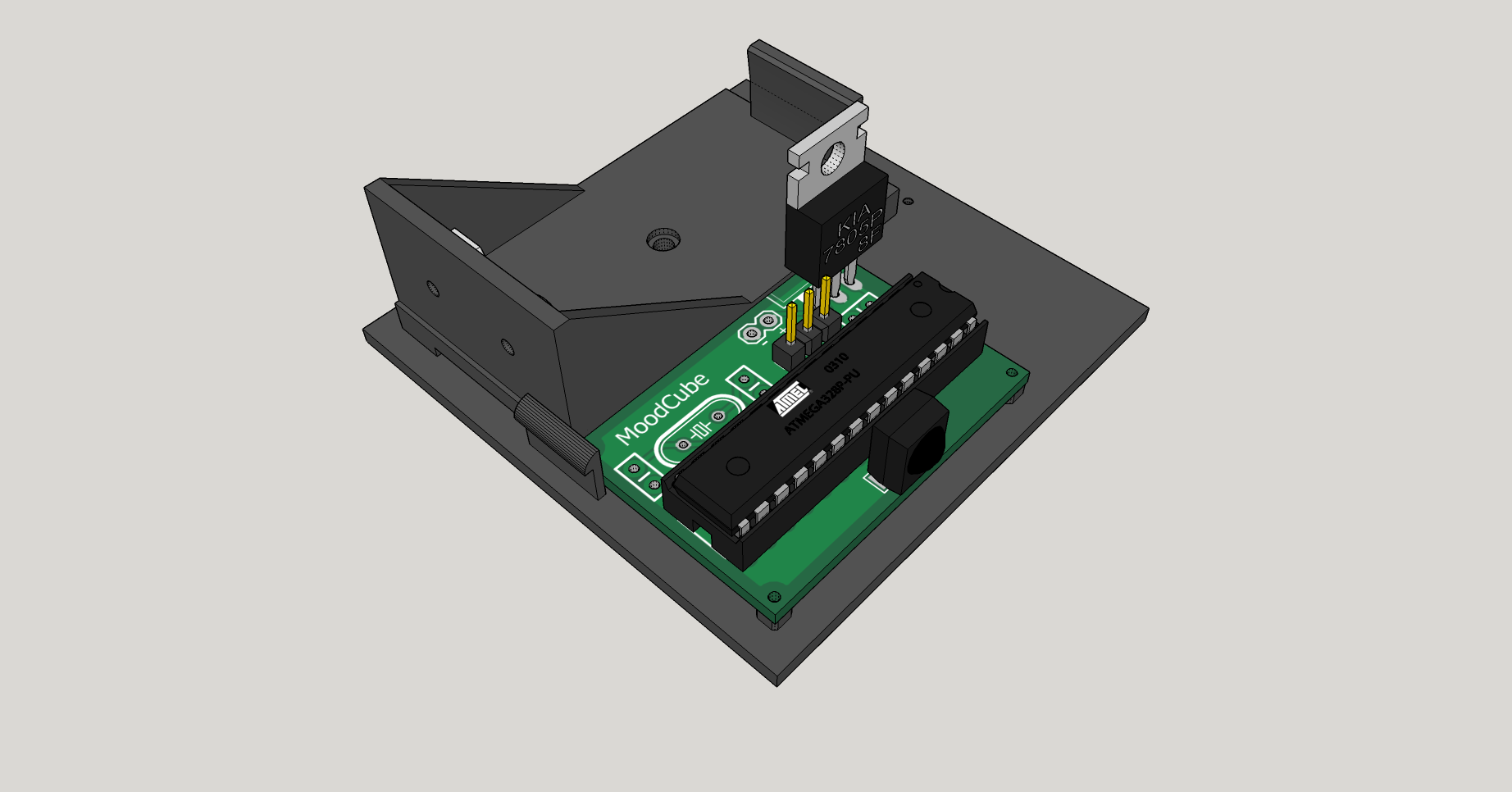
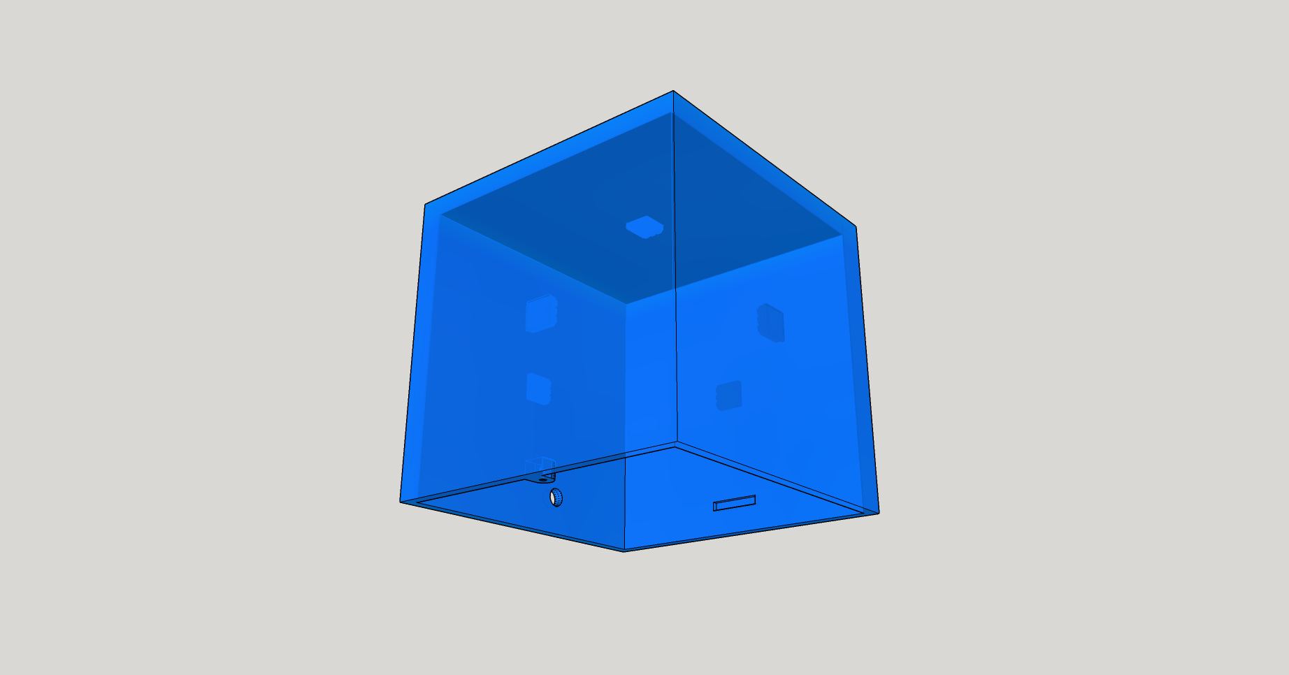
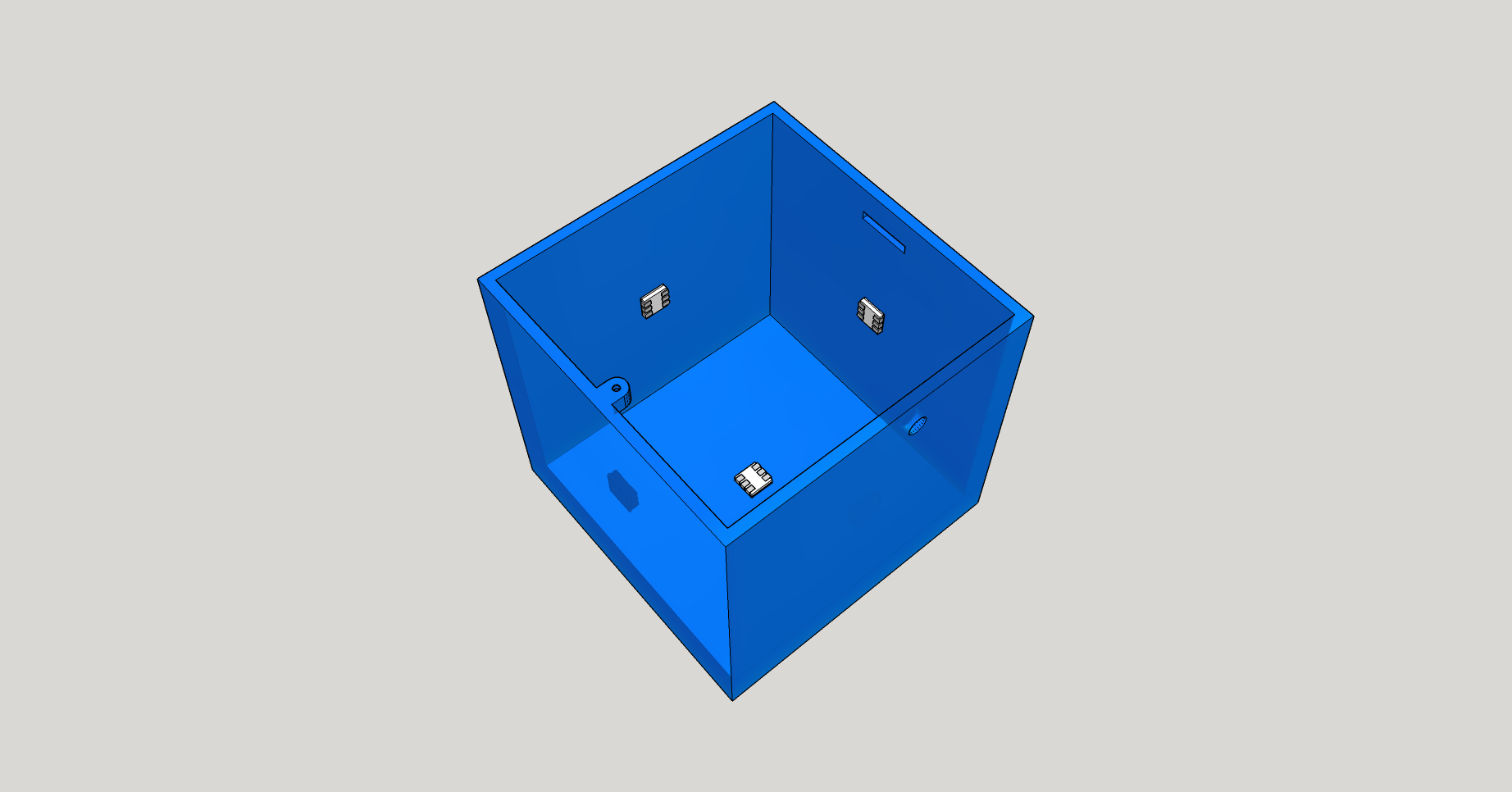
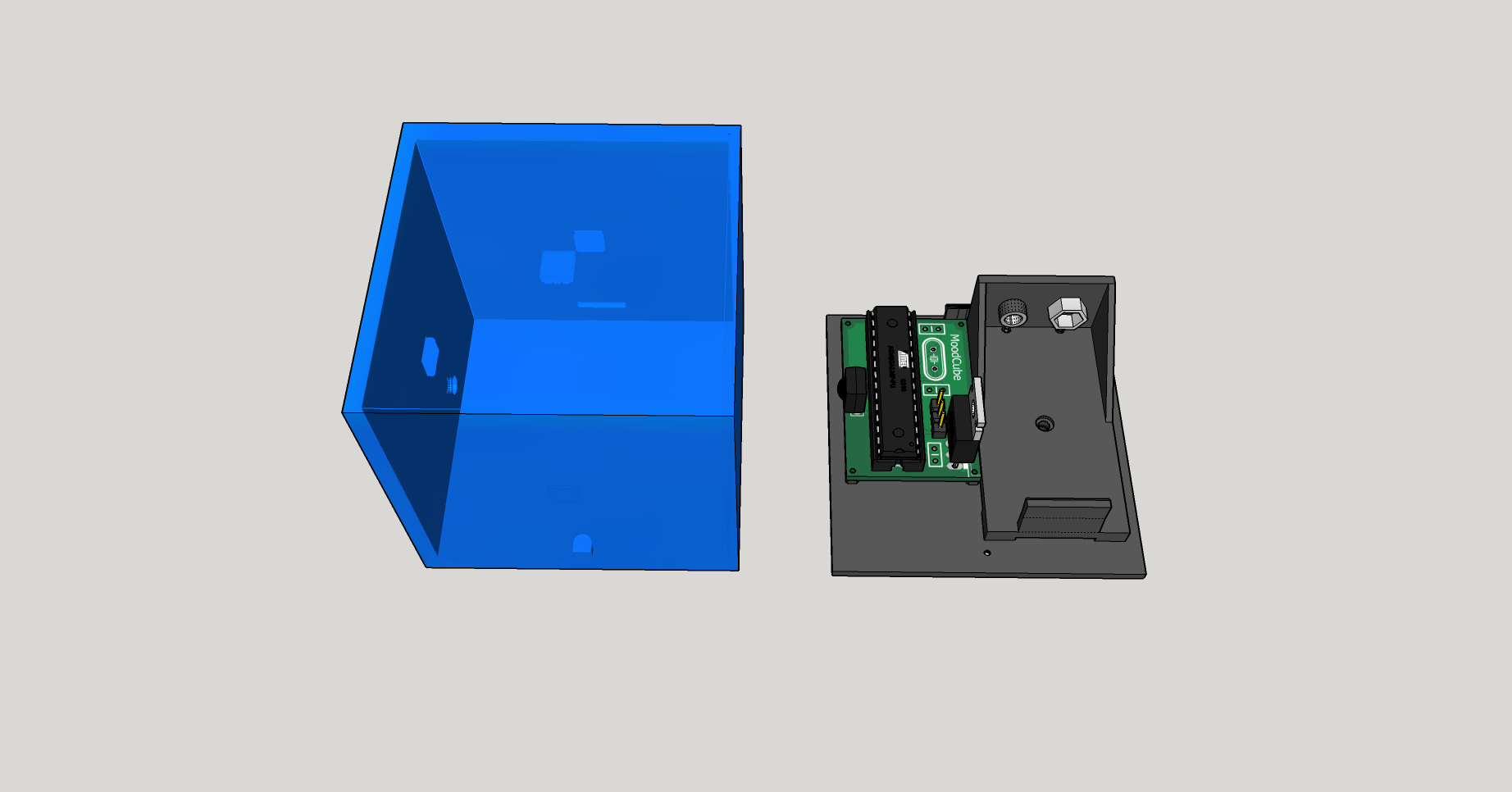
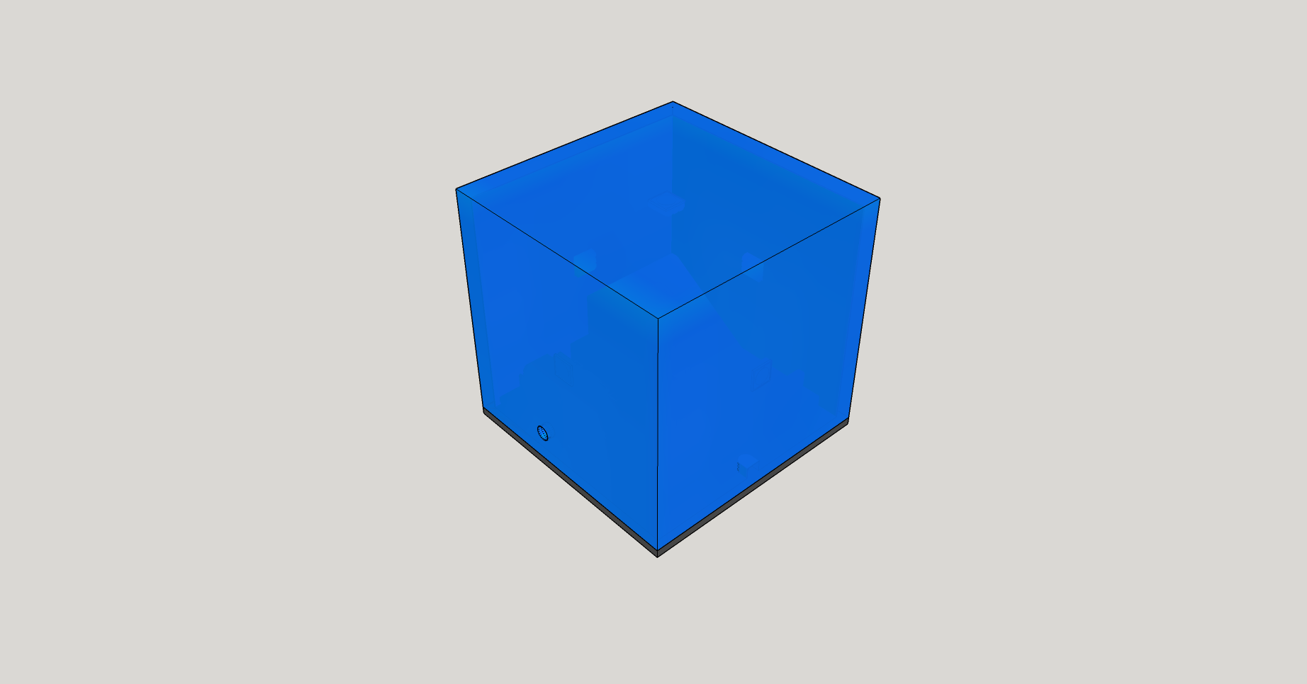
But let’s get back to our MoodCube ! What do we need ? Basically just a base to accommodate the circuit and the battery, and a cube coming on top of it acting as a light diffuser. White acrylic is a good pick for such an application, but standard PLA/PBS should do the trick as well.
The bottom holds to the top thanks to a single screw and little plastic piece that will fit into a slot made on the top part.
As for the battery holder, I didn’t bother too much and went for this model since I could find the 3d model of their product easily.
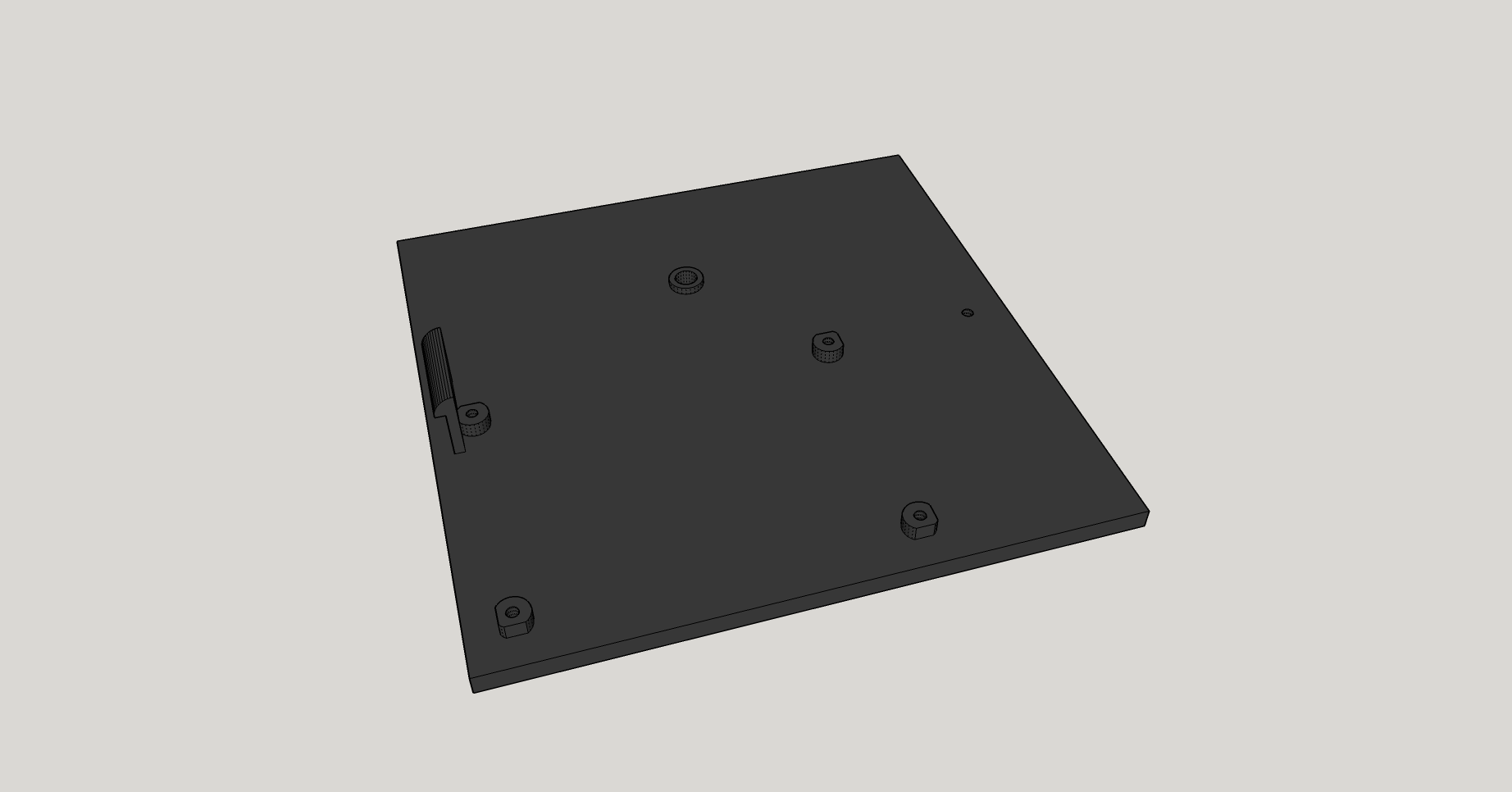
Here is the result. Once you are satisfied with your design you can use the Solid Inspector tool to check if your components are solids. If they pass the test, you can then export the model in .stl thanks to yet another extension and perform a last water-tightness test in Meshlab (or whatever CAD software you prefer).
All the corresponding files can be found here.
A piece of advice : make extensive use of the “Make component” functionality. This way if parts of your model are copies of one another, you’ll just have to modify one and the change will be applied on all copies of the component. Plus like in programming, modularity and re-usability is the key so it’ll really make your life easier.
Now we want to print our model right ? If you’re like me and don’t have access to a 3d printer, you will have to rely on someone else to do that for you. Having something 3d printed can get expensive pretty quickly depending on the volume of your model. I was a bit baffled by the price at first, and if you are too I’ll tell you the same thing I was told : you’re not only paying for the plastic used to print your part, but also for the time of the machine, the time of the machinist and the high depreciation of the value of the machine itself. + most of the time a little rework is performed on your model by the guy that prints it, so you have to pay for his expertise too.
That being said, keep in mind that printers don’t print at 100% density. Which means that if your model has a volume of 100 cubic centimeters and the printer’s rate is 1$/cc, you wont end up paying 100$. The filling density is usually between 15 and 40% (the more density, the more resistant you material will be) so you will be paying approximately between 15 and 40$ (their usually is a fixed starting price added to the variable one).
Shapeway is a big player in this area but I find that they are quite expensive. Personally I prefer to go on 3dHubs and look for a local actor. I like to that because you are in a strong position to negotiate : there seems to be a lot more people trying to make a little profit with their 3d printer than there is demand so they are being super nice to you in order to get good reviews and start a clientele.
Here ends my experience regarding this topic. I hope that you found what you were looking for, or at least some of it. If you would like to add something, please say so in the comments and I’ll gladly see to it.
Additional resources
- EEVblog video : PCB Design for manufacture (don’t you love this guy?). [Youtube]
- How to go from arduino prototype to selling product [Reddit]
- How to go from arduino to cheap mass production ? [Reddit]
- From arduino to full production [Forum]
- If arduino is for prototyping how to you make the actual product ? [Forum]
- From prototype to mass production [Forum]
- From prototype to kickstarter to production : the blink(1) development story [Slideshare]
- How to go from newbie to manufactured ? [Electronics.stackexchange]
- How to mass-produce an electronic system ? [Electronics.stackexchange]
- Some very informative reactions to this post [hardware.slashdot]
Edit 1 : on the good advice of [Milumet] from Reddit and other commentaries about my poor choice of voltage regulator I replaced the MCC7805CT by a L7800 and also added two capacitors on Vin and Vout as stated in the datasheet. Which leads me to a piece of advice I forgot to follow myself : always go look at the application circuits section of the datasheet of the components your are using.
+ tied the RESET pin to Vcc so that it’s not left floating. Why ? because a pin left in a floating state can jump from one state to the other because of the weakest surrounding electrical noise and we don’t want the MCU to reboot incessantly do we ? I had the case of a simple counter incremented by a push-button : the button was not inserted right in the breadboard so the pin was effectively floating and the counter would increment like crazy when I hovered my hand on top of the circuit. I was starting to believe that magic was real and expected a fairy to appear when I remembered : the pin was in a floating state, and the noise generated by my body was enough to get the pin’s state oscillating.
+ generated the corresponding gerber files.
Edit 2 : added OSH park to the list of PCB manufacturer since they were mentioned very frequently.
Edit 3 : added an electronics section to the Resources page.
Amazing article and workflow description. Thank you!
As for China, i’ve heard the same stories too. People always expect their hardware will be copied. The protection mechanism in use is software. Without the software (firmware, SaaS, app) the hardware is pretty much useless or it will take a long time for the copy to catch up in functionality and quality.
Software is easier to copy than hardware. Zero capital, few connection, no inventory or manufacturing or physical space needed. So software doesn’t seem like much of a mechanism or barrier if someone already has the means to copy hardware.
Thank you very much for your comment(s). Feeling useful for someone else is quite enjoyable!
I might be naïve to think like that but, if they are going to steal your design/code anyway wouldn’t it be pragmatic to negotiate a partnership with them beforehand ? They’ll gain a more stable technical support than what they would have been able to steal and would pay you royalties on the “cloned” units sold. + if your market is not colliding with China’s you’re not creating any competition.
One thing that comes to mind when I look for something that can’t be copied is a strong relationship with your user base, especially with an open source product. Nobody will be able to replicate the trust and the involvement of your customers (that is – if you succeeded at getting them involved in your development process), and you will be the only one having access to their awesome source of feedback.
Hot glue gun…. Done…
My thought on the Chinese hardware copying: build in a space for a through hole resistor, but do not give any indication of what kind it should be. Use a socketed ATMega chip for your productions, and flash all those yourself with a programmer in your own lab. For the through hole resistor, use a very specific value of metal film resistor, and have your program “check” it before being able to start up. Run out of resistors? No worries, you can just change the code to accommodate a different resistor. You could even do several resistors on the board this way for a “combination” lock.
that’s a very smart -and simple- way to deal with this problem thank you for the advice !
i am working on a project based on sensors , for the prototype i have developed on arduino board . i would like to create a pcb instead of arduino board .
please help to solve my problem
Alexis,
Great post! It really fits well with a new podcast I’ve launched called “Gears of Resistance” .. it’s dedicated to OSHW news, electronics tips and advice on launching a business built on OSHW. Would you consider being a guest? Check it out at gearsofresistance.com
A great book on outsourcing to China is “Poorly Made In China”. It’s not about doing electronics, but a friend of mine who had managed several electronics products that were built over there said it was dead-on. Here’s the link to Amazon:
http://www.amazon.com/Poorly-Made-China-Insiders-Production/dp/0470928077/ref=la_B001Q4AHF2_1_1_title_0_main?s=books&ie=UTF8&qid=1432001592&sr=1-1
As soon as I’m done with Critical Path by Buckminster Fuller I’ll start this one. After all the reactions on the subject, I’m really not looking forward to have to deal with the Chinese (no offense intended for any chinese reader, I’d be very happy to be proven wrong on that point…).
Hey buddy sweet post.
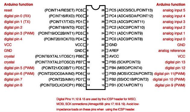
I did miss a pretty important step here. Once I´ve my code written in Arduino, how do I program the ATMega328 ?
Thank you, I hope it can be useful.
What I did was to use an Arduino Uno to program the chip: put the chip in place, flash the code from the Arduino IDE or whichever and pop the chip out. It’s fine if you just have to flash once but if you flash a few times you run into the risk of damaging the legs of the chip.
You can also program the chip outside the socket by connecting the RX and TX lines from the UNO:
https://www.arduino.cc/en/Tutorial/ArduinoToBreadboard
Another solution would be to use an AVR programmer to upload the code directly to your chip on the breadboard by connecting a few cables.
http://www.instructables.com/id/Atmega-Programming-with-USBtinyISP-and-Arduino/
https://www.sparkfun.com/products/9825
Awesome! Thank you very very veryyy much!
cool article
How you update the software!? Only in prototype phase!?
Fact: The Chinese manufacturers will quickly copy anything and everything they are given to make, then “cheapen-ify” and cost-cut it, often at the expense of life and performance. Then they will sell it into your market to your competitors and even through your own retail channels, if you are a wholesaler. They have no issues over doing any of this, so protect yourself as best you can. But plan for the worst.
One month ago, I knew JLCPCB from pcbshopper, I am pretty happy with the boards I received from https://www.jlcpcb.com, and the price is cheaper than most of other pcb production factories. The 100% E-testing was very nice too. I just finished ordering our second set, and now, waiting my PCB and start my new project.