Prologue
I’ve never really considered connecting my projects to WiFi since the price of the shields was so high. The HUZZAH from Adafruit will set you back $39.95. Sparkfun sells this shield for $84.95. Way to expensive.
So you might imagine my excitement when I first heard about the ESP8266 through hackaday. A WiFi module for less than $5, that sounded ideal. I started to read about it, checking out the projects that flourished around this newcomer. It seemed easy enough to use, and I was already imagining how I would start this article. Something like :
“Meet the great ESP8266, a low cost, plug&play device that will allow you to easily connect your projects to the web”.
But things did not go as planned…The first module I bought was defective, and it almost drove me nuts trying to figure out what was it that I was doing wrong. When I started to think about leaving electronics behind forever and starting a new life as a shepherd in South America, I decided that spending an additional five bucks for a new module just in case mine was broken from the start was not too much.
Did my torments ended here ? No they didn’t. If you’re not careful with your set up (jumper wires well in place, power line decoupled, enough current etc.), the ESP can (and probably will) get very unpredictable. But don’t despair. Hopefully for you I’ve fallen in the most common pitfalls so I’ll try to detail them so you can avoid insanity. And it’s really worth it once you figure out how to operate this thing properly. You can check out the result on my Thingspeak public channel.
What we will be making
As you might have already guessed from the title, we are going to make a shield for the Arduino Uno. The shield will hold 3 sensors used to collect environmental data : temperature, barometric pressure, humidity and luminosity. The data will be sent online using the ESP8266 module. The module runs on 3.3v and requires about 300mA to run properly which implies two things. First that the 3.3v pin of the Arduino will not provide enough current to power the ESP (it only delivers 50mA) so we need a voltage regulator in order to tap in the 5v power line. Also that the logical voltage of the Arduino is too high for the ESP. We will see how to circumvent this drawback.
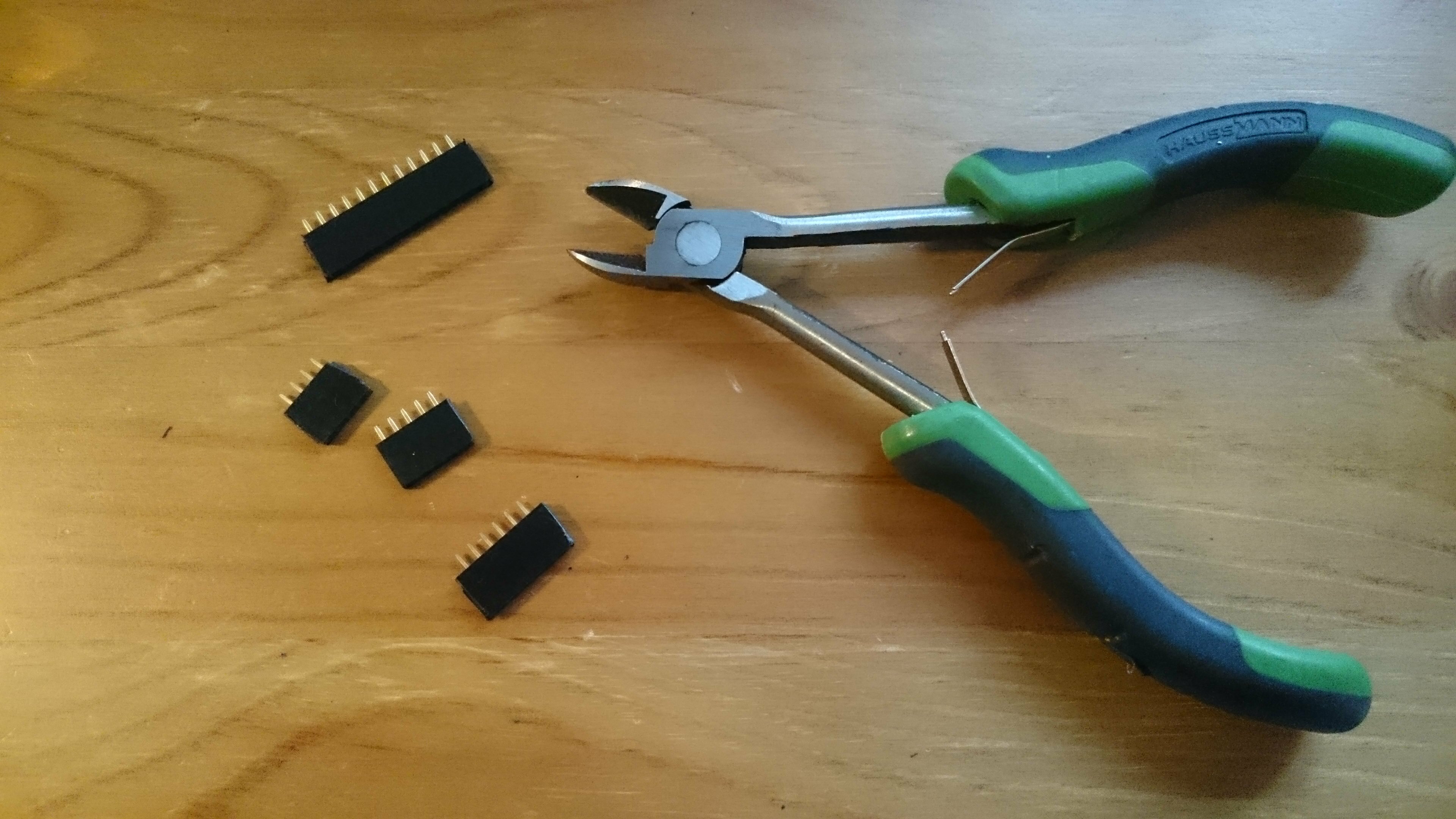
In order to be able to re-use the different modules used for the shield in different projects if need be, I chose to use female headers so that I can plug/unplug them at will. I didn’t use individual headers but bought a large one that I cut into pieces. Since you lose 1 pin for every cut, you need at least a (5+4+2*6+2*4)+6=35 pins header with this method.
Table of content
- Part 1 : The ESP8266.
- Part 2 : The sensors.
- Part 3 : The circuit.
- Part 4 : Pushing data online.
- Sources.
Components list
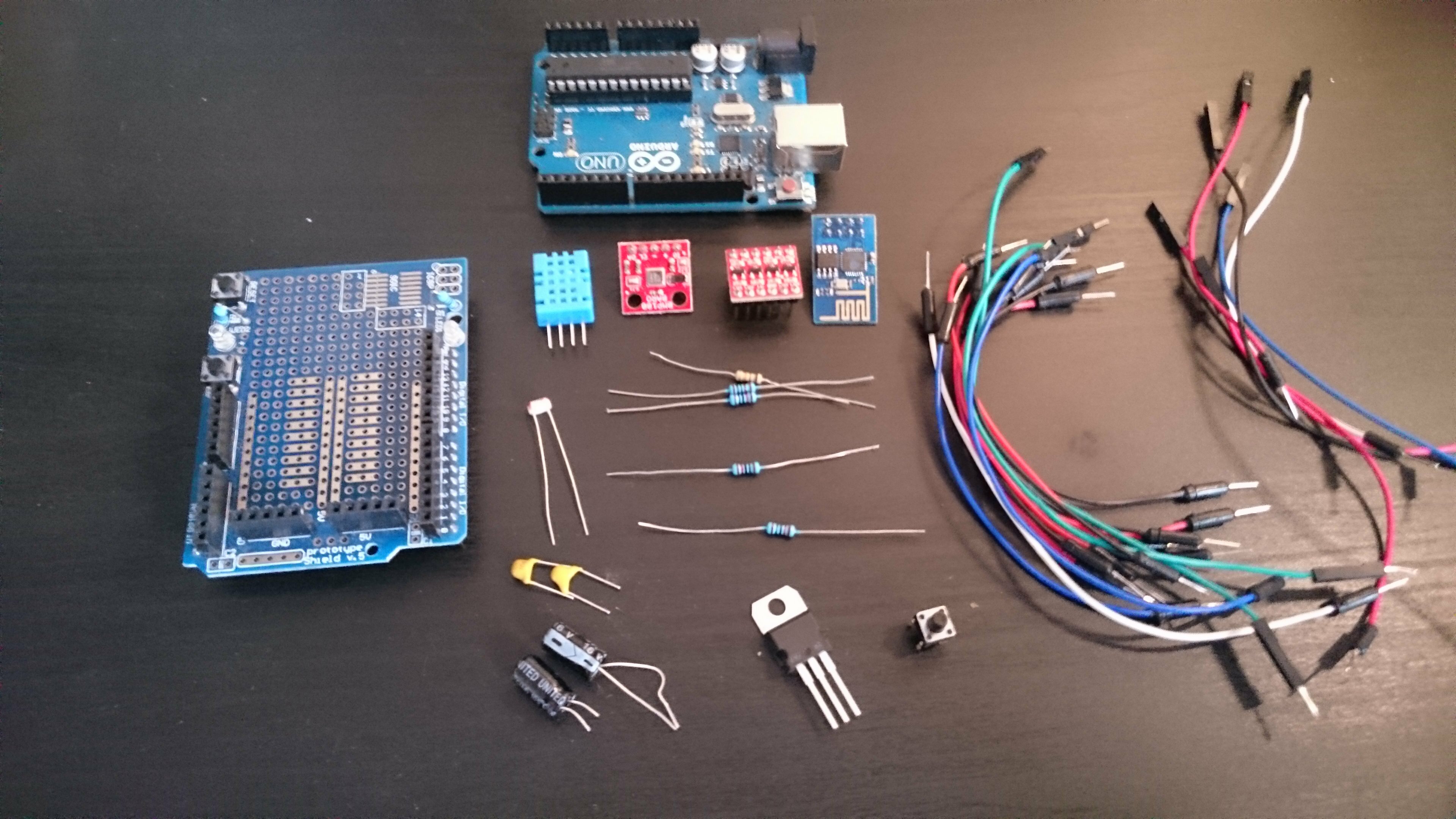
- 1x Arduino Uno
- 1x Arduino prototyping shield
- 1x ESP8266-1 wifi module
- 1x bi-directional logic level shifter
- 1x DHT11 humidity and temperature sensor
- 1x BMP180 barometric sensor
- 1x photocell
- 1x LD1117V33 voltage regulator
- 1x 100nF ceramic capacitor
- 1x 10uF ceramic capacitor
- 2x 470uf electrolytic capacitor
- 4x 10kOhms resistors
- 1x pushbutton
- 1x female header (>35 pins)
- male/male jumper wires
- male/female jumper wires (to connect esp)
- breadboard
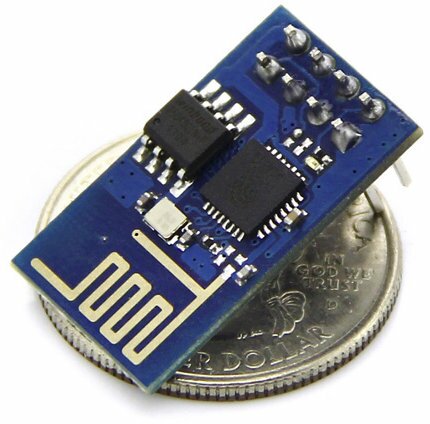
The ESP8266
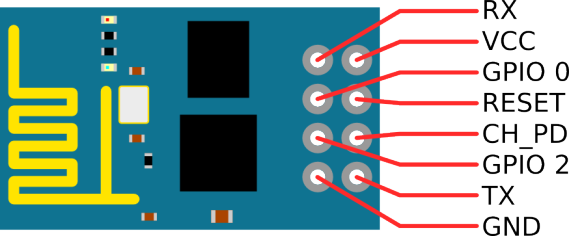
Tx : Serial send
Vcc : 3.3v
GPIO_0 : floating. grounded to enable flashing mode
CH_PD : 3.3v. chip enable (low)/power down(high).
RESET : 3.3v. ground to reset chip
Preliminary advice
As I was saying in the introduction, the module can become your worst nightmare if you don’t use it properly. Because the problem is not that it wont work at all, but it will work incredibly erratically. Which is a synonym of hell if you’re a very logical person trying to come up with logical explanations to your troubles. Trying the exact same set up a day apart would yield completely different results, the response time would variate, it would reboot switch to a busy state for no reason etc. You don’t want that. So here are some advice before starting :
- The ESP8266 is a 3.3v device : do not try to power it with 5v and do not hook it up directly to 5v rated pins (like the digital and analog pins of the Arduino Uno). I’m not saying that it will burn your module instantly, but if you have troubles in the (probably near) future you’ll never be able to know if you damaged your module doing so or if the problem comes from something else.
- If you can’t communicate with the ESP and the blue light is flashing continuously, it means that one (or both) of your lines of communication (Rx&Tx) is not plugged in correctly.
- On the breadboard, double and triple check your jumpers if the module is behaving somewhat mysteriously. Very often my problems have been solved that way.
- Use decoupling capacitors on the power line to which the ESP is connected to. It’s really sensible to variations in its power supply so better be safe than sorry.
- Depending on your firmware, the baudrate can be different. From the ones I have tested it was either 9600 or 115200b/s but it could be something else. If your device is printing gibberish to the console, try to change the baudrate.
- This is more a of general advice, but always read the datasheets. How many times did I came back home eager to try out new components, I plugged everything on the breadboard only to wonder at the strange reactions I was observing when a simple look at the datasheet would have told me that my device needed more current/a specific decoupling capacitor etc. Even if you’re new to this and a bit impressed by all the informations on these documents, fear not as it will come quickly to you. You’re always looking for the same things anyway : the typical supply voltage, current and the application circuit.
Talking to the esp
This is the first thing we need to do in order to verify that our module is working as it should be. The first method detailed below interfaces directly with the ESP so you will only need a Serial console. You can use the console of your choice like the one included in the Arduino IDE. Putty works well too. Personally I use Atmel studio with Visual Micro for all my embedded development needs.
If the console doesn’t suit you, you can use use this very neat program which provides a proper UI in order to test the module.
For the parts involving Arduino, you will need to upload this code. It uses the SoftwareSerial library to bring a second Serial to the Uno using two digital pins. This is done so that we can reserve one Serial to print debug messages on our end, and the other to communicate between the Arduino and the ESP. Everything entered from the USB to the Arduino in the hardware Serial is pasted in the SoftwareSerial and goes to the ESP, as well as the other way around.
The ESP accepts a variety of commands that always start with the prefix “AT”. After that the module has executed the command received, it usually sends back a response code (“OK” for most operations, “0,CONNECTED” when a TCP connection is open, “ready” after a reset etc.). Some of the most common are AT used to check if the ESP is responding correctly, AT+GMR which outputs the version of the firmware, AT+RST to reset the module, AT+CWJAP="SSID","PASS" to join an access point. Here is a rather complete list of the AT commands and here is a pretty handy one. The commands can be slightly different between firmwares so keep that in mind.
Use one of the methods presented thereafter to connect to your ESP. Once your circuit is set-up, here is a little “Getting started” script to test your device. I’m using a firmware version 0.9.4 so again your commands and response codes might be a bit different.
| Command | Detail | Expected response |
|---|---|---|
| AT | Is ESP available ? Will answer ‘busy…’ if unavailable | OK |
| AT+GMR | Get firmware version | 00200.9.4 compiled @ Dec 24 2014 20:44:10 AI-THINKER Dec 24 2014 |
| AT+RST | Reset ESP |
OK
ready |
| AT+CWMODE=1 | Set ESP as client (2 for server, 3 for both) | OK |
| AT+CWLAP | List available access points |
+CWLAP:(2,”TP-LINK_954D62″,-90,”f8:d1:11:95:4d:62″,2) +CWLAP:(3,”ARTDECO”,-86,”ac:81:12:ea:17:64″,2) +CWLAP:(4,”captainblood”,-87,”ac:f1:df:62:65:3f”,6) OK |
| AT+CWJAP=”A_P_NAME”,”PASSWORD” | Join access point | OK |
| AT+CWJAP? | Get current access point | +CWJAP:”A_P_NAME” OK |
| AT+CIFSR | Get current IP |
+CIFSR:STAIP,”192.168.2.36″ +CIFSR:STAMAC,”18:fe:34:9f:49:a0″ OK |
| AT+CIPSTART=”TCP”,”www.google.com”,80 | Open TCP socket on hostname/IP with port chosen | 0,CONNECT |
| AT+CIPSEND=23 | Announce the number of bytes that are going to be sent | > |
| GET / HTTP/1.0\r\n\r\n | Request body | SEND OK |
| AT+CIPCLOSE | Close tcp socket | 0,CLOSED |
FTDI Breakout
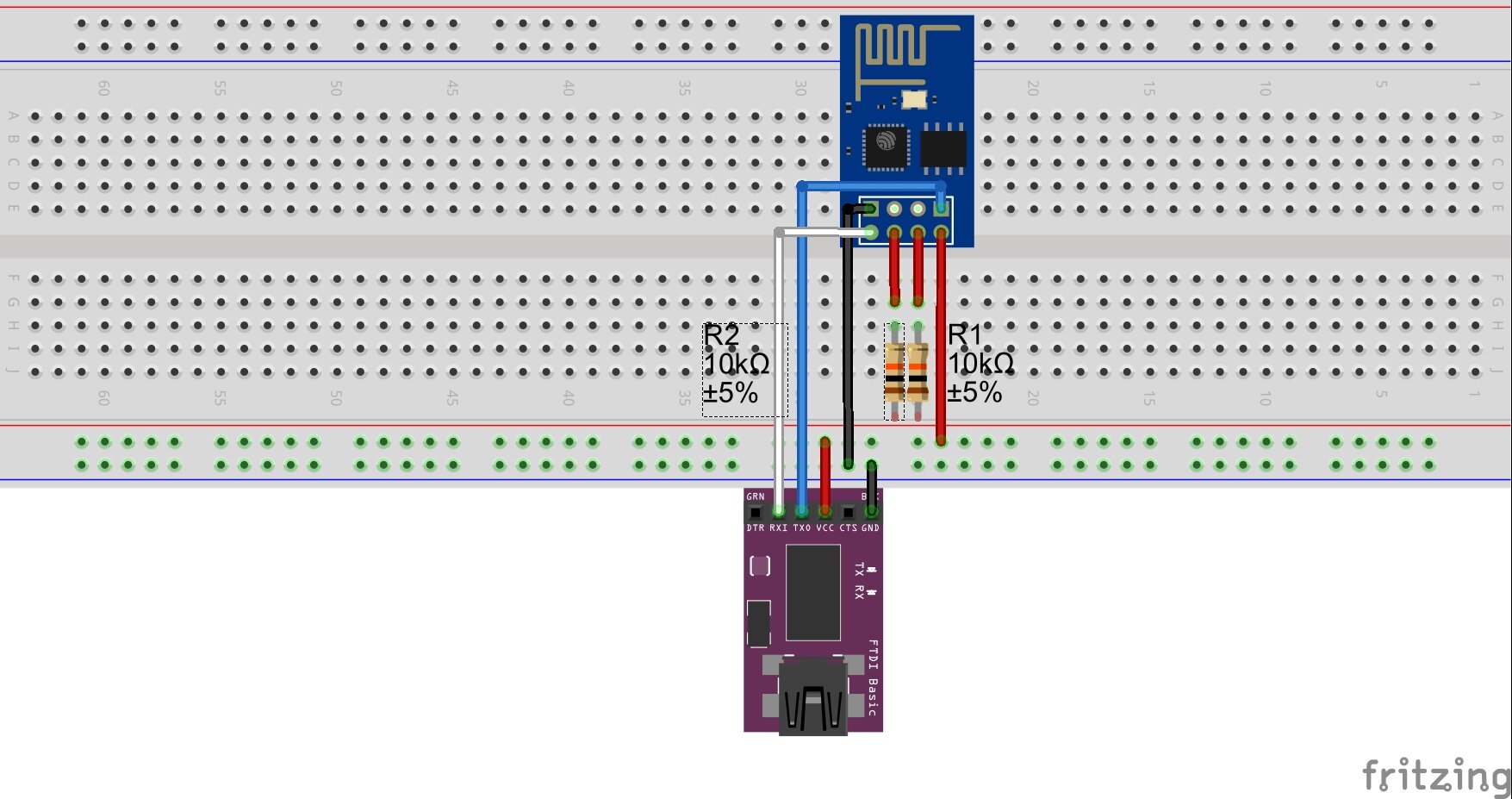
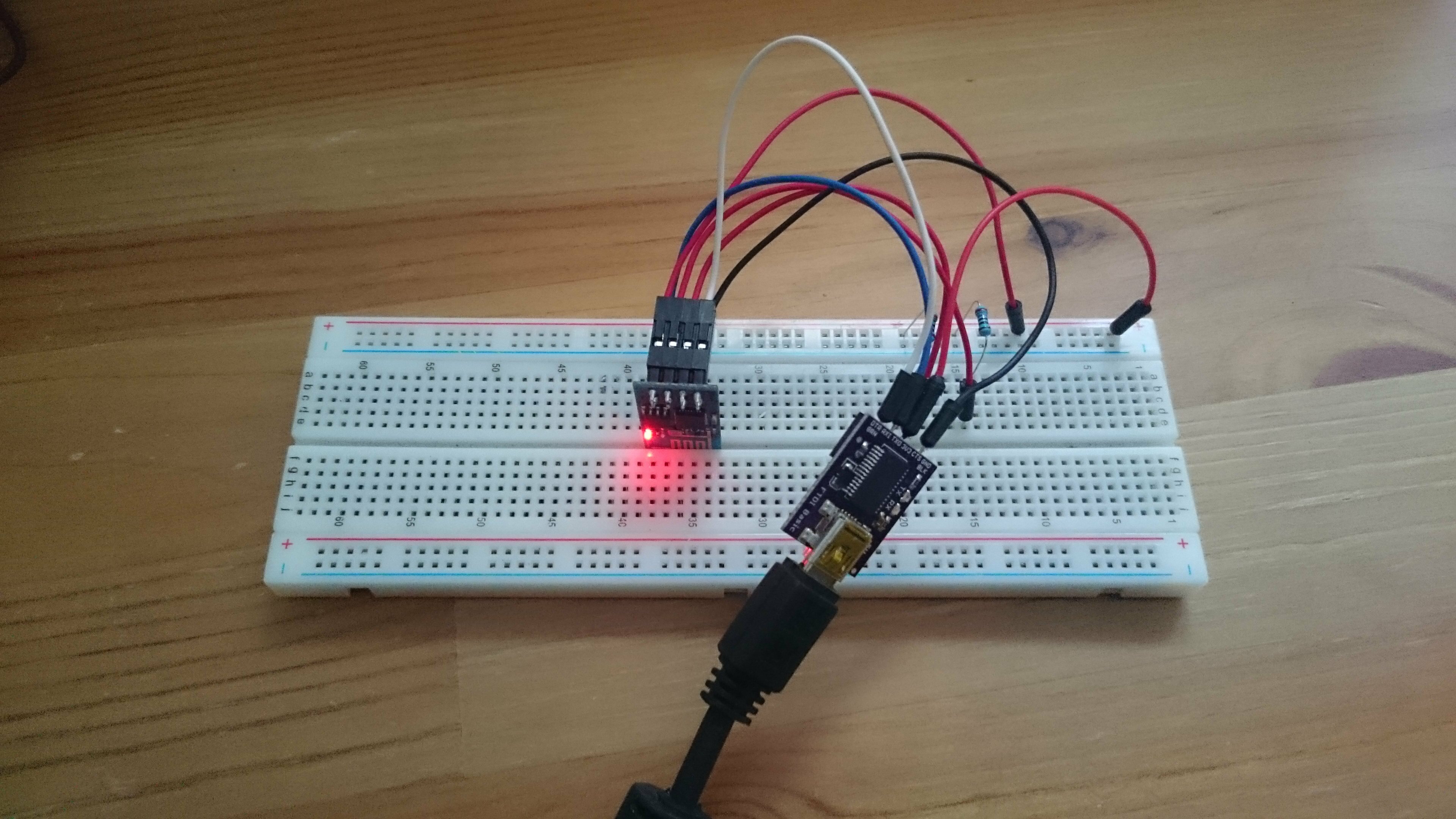
The FTDI Breakout is used to directly connect to the Serial line via USB, no code needed. This is by far the easiest way to get started. The model I use allows to switch its operating voltage between 3.3v and 5v which is convenient. In any case, ensure that you are using a 3.3v device.
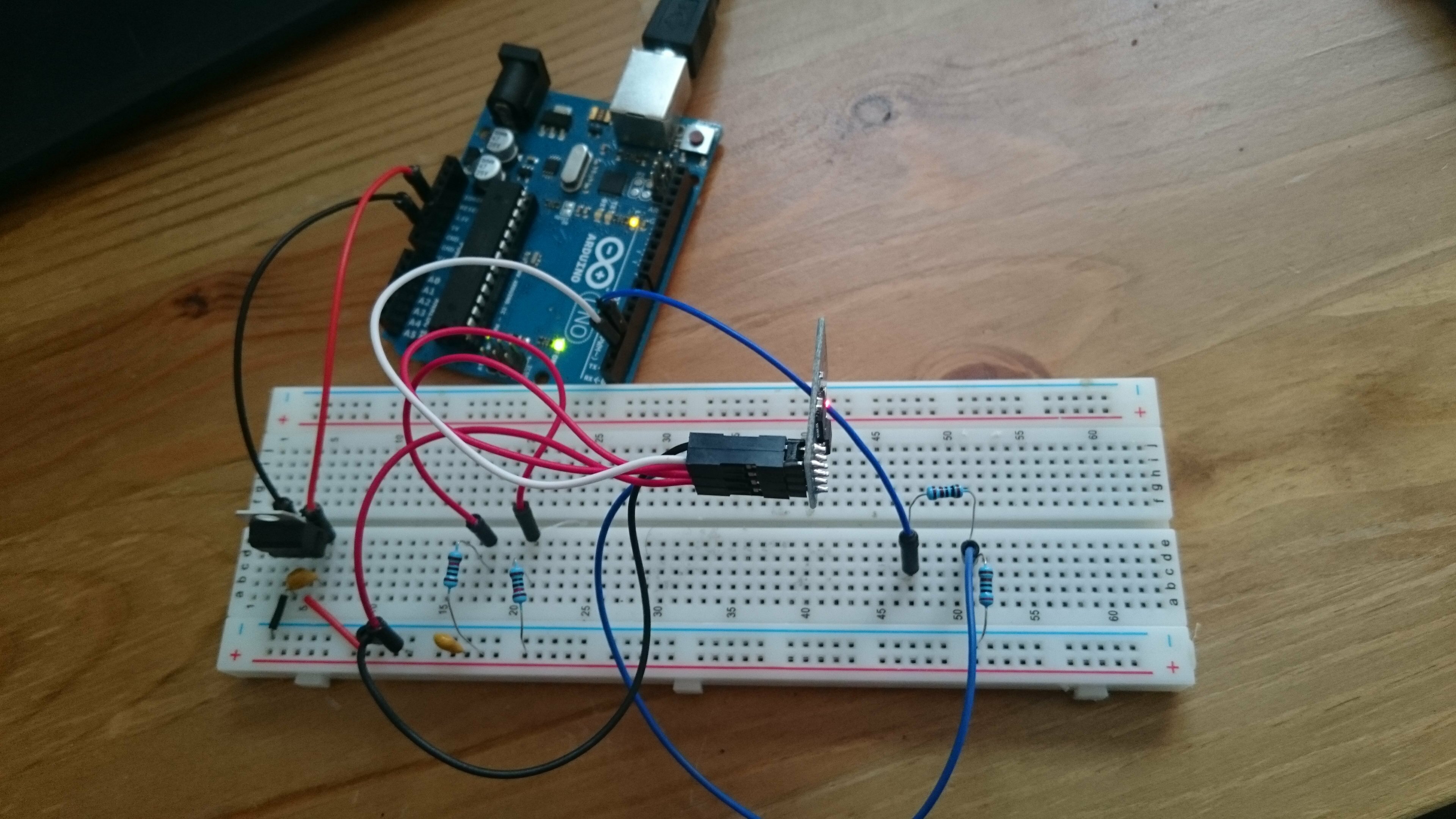
The Rx and Tx pins have to be cross-connected between the devices. This is because what is being sent (on Tx) by one device needs to be received on the receiving line (Rx) of the other device and vice versa. Pretty logical. So Tx (ESP) goes to Rx (FTDI), Rx(ESP) goes to Tx(FTDI). CH_PD (chip enable/power down pin) must be pulled up to 3.3v, as must be RESET. In both cases we will protect the pins with two 10k resistors. Once again, better be safe than…yeah you know the drill.
Arduino – voltage divider
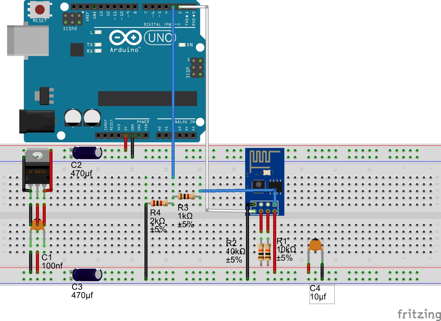
Here we will use two resistors to create an output voltage that is only a fraction of the input. The formula is Vo = Vin * R2/(R1+R2). With Vin=5, R1=1k and R2=2k, Vo = 5*2/(1+2) = 3.33v. Hey, that’s just what we need! You can use other values for the resistors, so long as the ratio R2/(R1+R2) stays the same.
If you want to learn more about the voltage divider circuit, have a look here. The circuit implemented here is slightly different than the one on the sparkfun page in that Vin and Vout’s positions are reversed. But worry not, it works just the same.
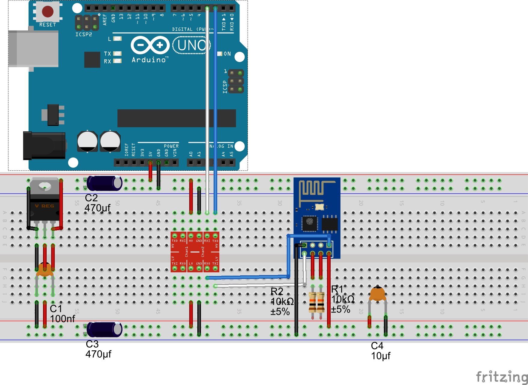
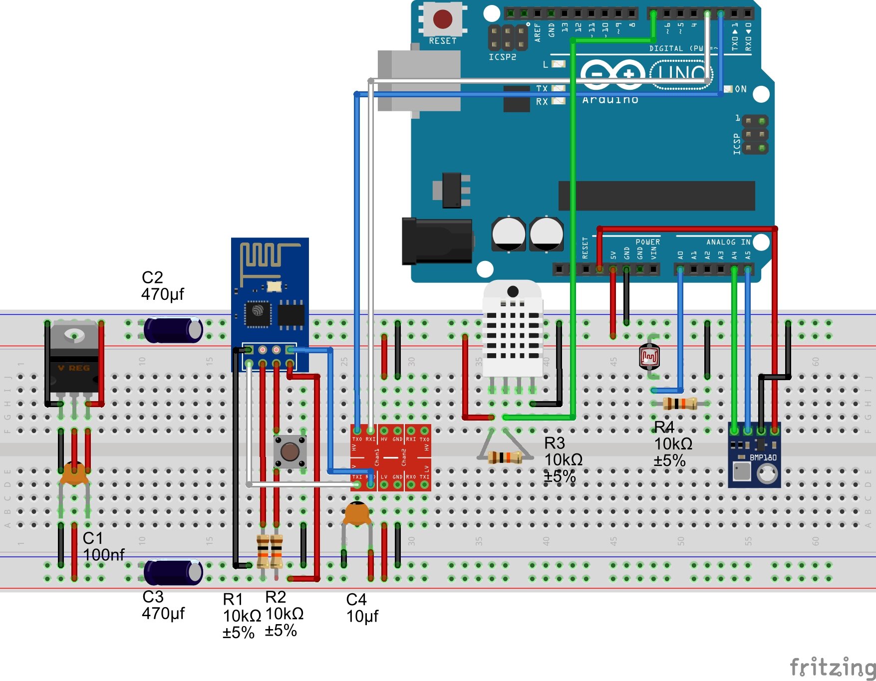
As we said earlier, we can’t use the 3.3v pin of the Arduino to power the ESP because the current delivered wouldn’t be enough. This is why we use a voltage regulator to tap the 5v power line and step it down to the 3.3v the ESP needs. Two decoupling capacitors are placed on each side of the regulator. C1 and C4 are advised on the regulator’s datasheet. C2 and C3 are here as an additional precaution. The closer C4 is from the ESP power pins, the better.
Arduino – logic level shifter
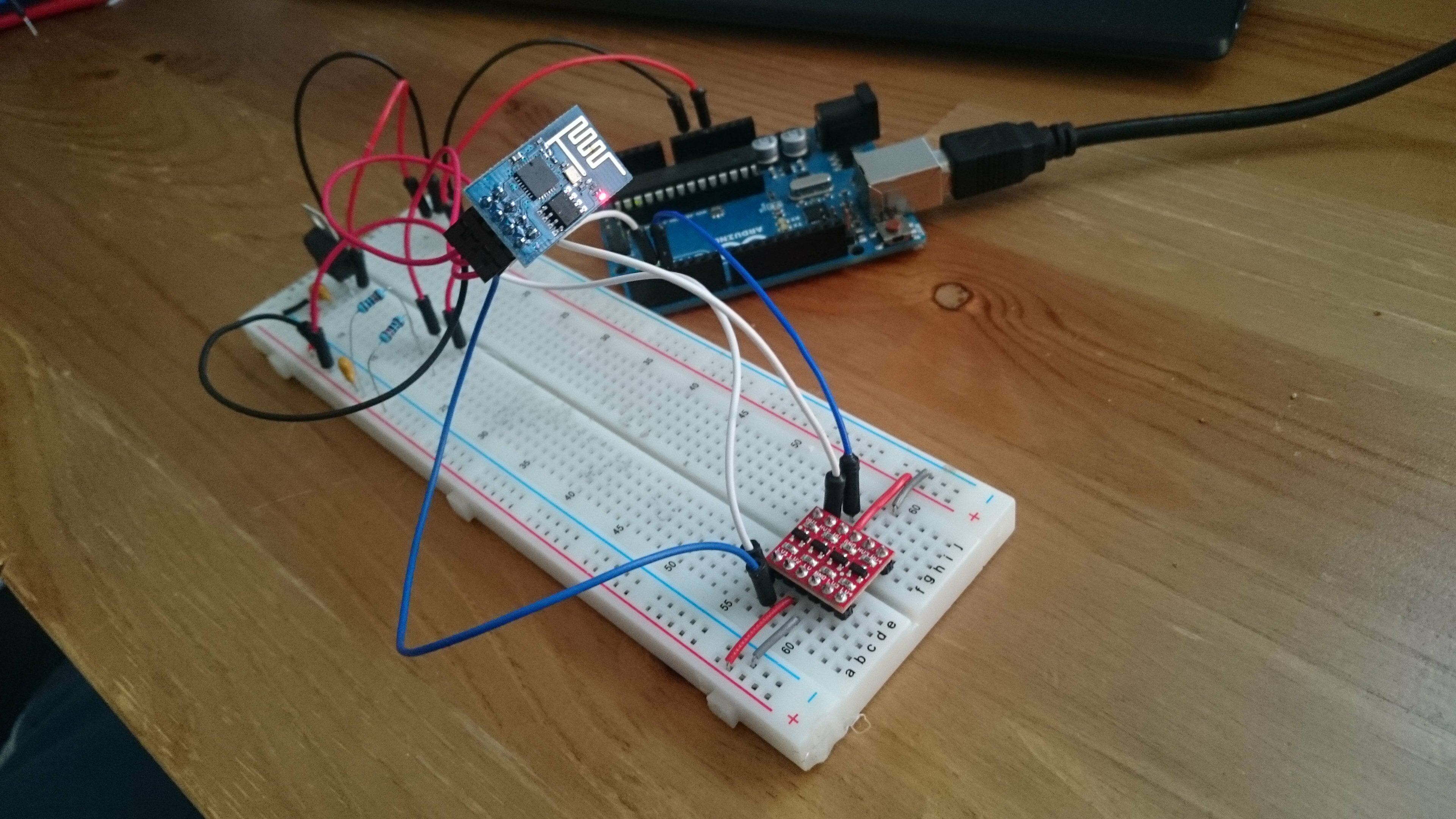
Also called logic level converter, this device is used to step up a signal from a lower voltage to a higher voltage as well as to step down a signal from a higher voltage to a lower voltage. The central pins are used to connect each side to a power source of the target voltage. In our case, 5v on the high side which will handle communication signals to and from the Arduino, 3.3v on the low side which will be connected to the ESP.
Once again sparkfun provides a nice introduction to the concept right here. Note that the model they use for their demonstration is a little different than mine in that all their pins are not bi-directional.
Arduino – 3.3v native logic
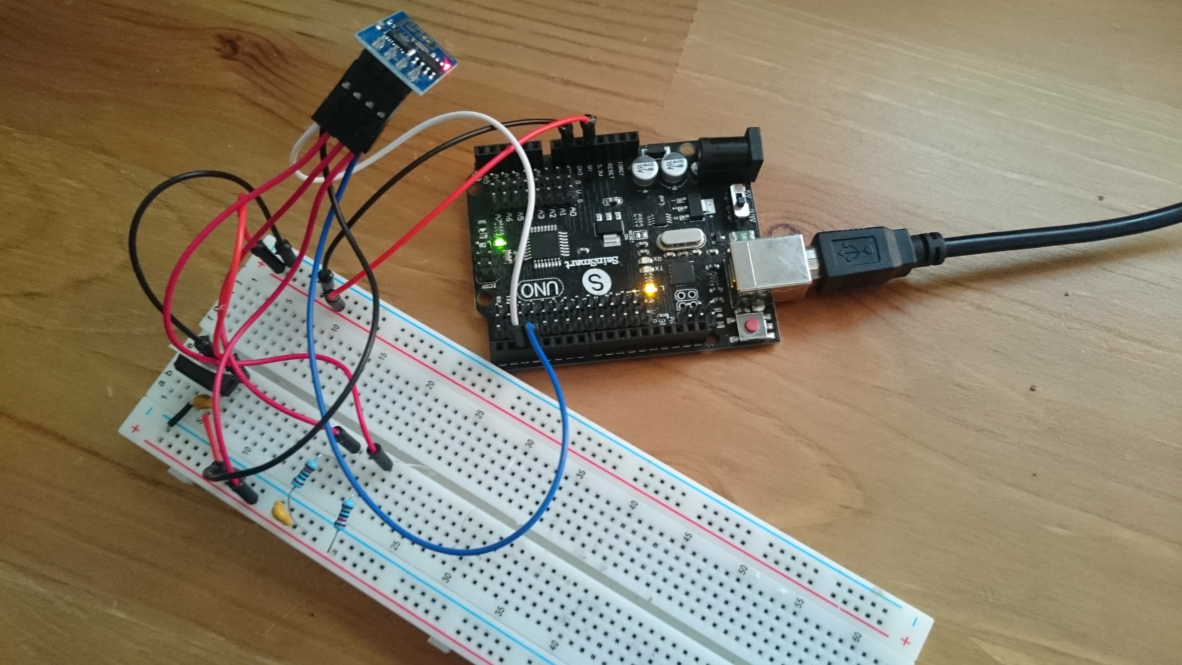
Finally you might be lucky enough to possess a version of the Arduino that allows 3.3v logic. Either natively like the Arduino pro mini or this clone from SainSmart that allows to alternate between 5v and 3.3v logic voltage with a slide switch. I like this solution because it takes some variables out of the equation which is a relief when you have to debug the circuit. I went toward a more general solution because I wanted to make the tutorial as accessible as possible but I would gladly have omitted the level shifter.
Flashing the firmware
Why would would want to install a new firmware ? Maybe everything else failed and you suspect a corrupted factory set-up. Or maybe are you interested in using the NodeMCU Lua interpreter. You could as well wish to match your firmware to the one on which a specific library was based.
The sum it up : reasons.
A firmware install is not very complicated to perform. Remember to connect the GPIO_O pin to ground and to reset the ESP so that it boots into flashing mode. Use the FTDI breakout to communicate directly with the ESP.
After that take your pick at an esp flasher program. This page introduces some of them. For NodeMCU you have NodeMCU flasher. I put the one I used and several firmware .bin files over there but be warned, I comes with no guaranty whatsoever. Check the sources to see where it comes from.
If you’ve survived to this first part, the rest should be easy. If you could address your ESP and it responded correctly we can assume that the communication part of the project is ready. Let’s set it aside and test our sensors.
The sensors
3 sensors will be included to our shield :
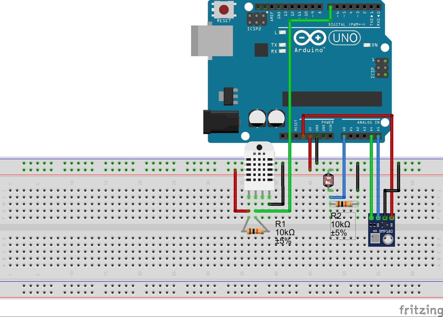
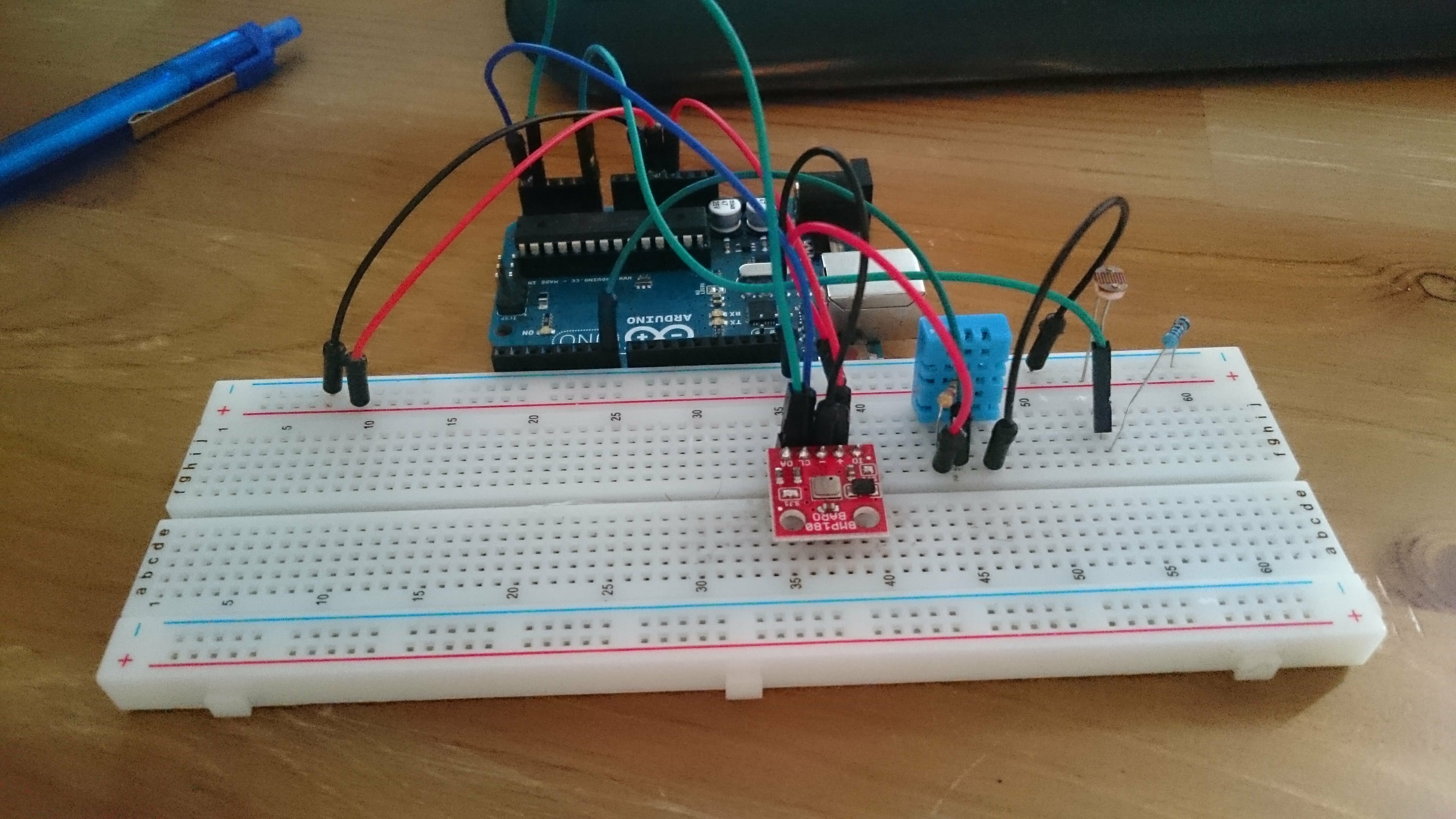
- BMP180 : a precision sensor from Bosch which can be used to measure barometric pressure and temperature. It uses the I2C protocol to communicate so it connects via the A4 and A5 pins. It’s a 3v device but 5v compliant thanks to an on-board regulator so you can power it both ways. I powered it with the 3.3v pin because I wanted to relieve the main Vcc but the datasheet indicates consumption peaks at 65mA which is 15mA more than the rating of the pin so it might not have been the best idea (full disclosure).
- DHT11 : a very cheap temperature and humidity sensor. Its big brother the DHT22 is more precise but also twice the price. I don’t trust it that much which is why we only use it to get humidity values. The library has a method to compute the heat index provided temperature and humidity which is nice. It is used with a pull-up resistor between Vcc and the data pin.
- Photoresistor : the resistance of this component is inversely proportional to the intensity of the light it receives. We use it in pair with a pull-down resistor. Why ? Because the analog input is high impedance. This means that if it was connected directly (through the photoresistor) to 5v, almost no current would flow. With the pull-down resistor, the current flows from 5v to GND and the analog pin picks up the voltage very well like we intend it to. The voltage measured at the analog pin is determined by the same equation we saw earlier with the voltage divider, namely Vo = Vcc*R/(R+RPhotocell). When the light gets brighter, RPhotocell drops and with it the denominator of our ratio. Vo will increases until RPhotocell reaches 0 at full brightness. At this point Vo = Vcc = 5v. In the dark, RPhotocell is almost infinite and thus Vo = 0. With a 10k pull-down resistor, the measurement will be less prone to saturate in a bright set-up. Inversely a 1k pull-down will be more adapted to a darker environment.
These sensors are very popular so you won’t be in trouble trying to find additional informations (start in the sources).
Code
Once your circuit is all set-up and you’ve double checked your jumpers, you can upload the following code. I only wrapped up together the examples from the different libraries implicated. The values are polled every 2 seconds and printed to the Serial console.
The output to the console should be something like this :
Readings from DHT11 :
Humidity : 33.00 %
Temperature (C) : 32.00
Heat index : 31.19
Readings from BMP180 :
Temperature (C) : 35.30
Pressure (abs) : 1015.59
Pressure (corrected for altitude) : 1033.47
Readings for luminosity :
96 %
The circuit
Testing the circuit on breadboard
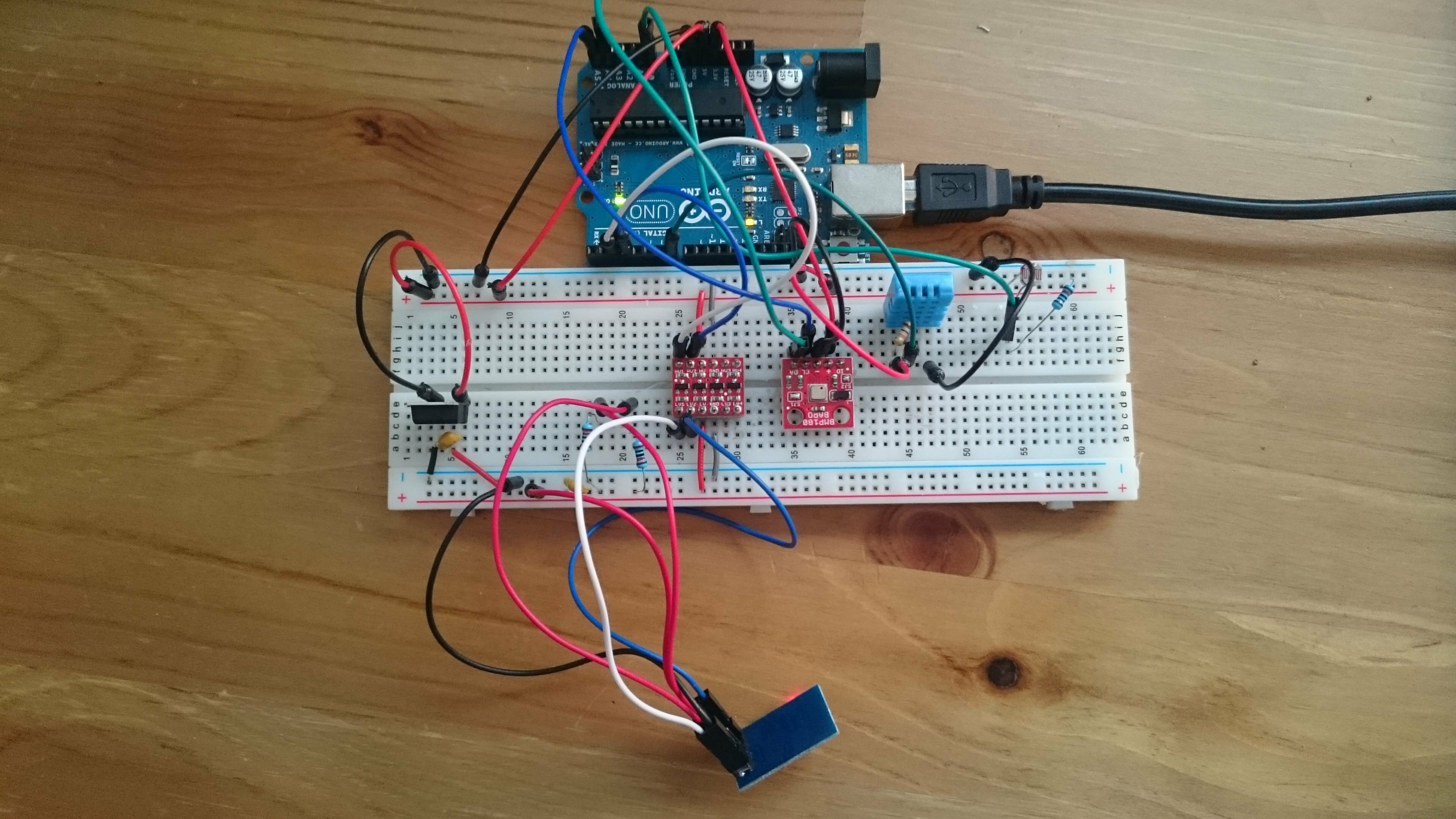
It’s time to put everything together. I chose to use the level shifter in the final circuit because it seemed like the best man for the job. The circuit is exactly the same as what we had been doing before, except for the addition of a push-button so that we can manually reset the chip easily.
Once you’re done with your little jungle of wires, you may want to skip the next part for now and jump to the final part in order to test your set-up before permanently soldering anything.
Making the shield
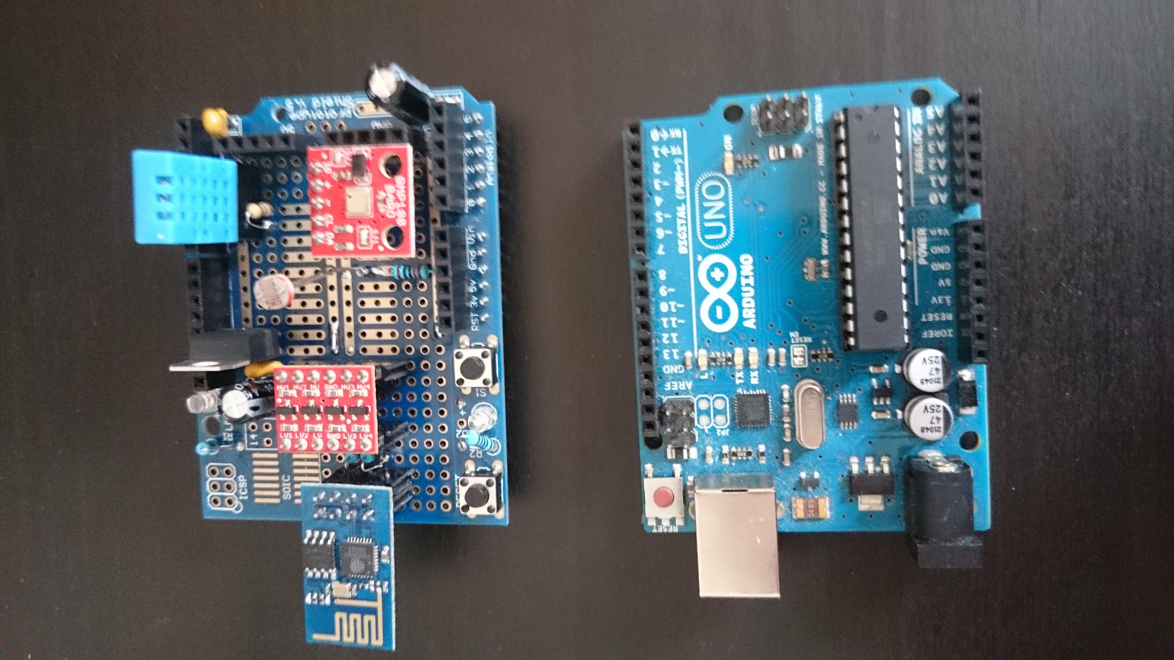
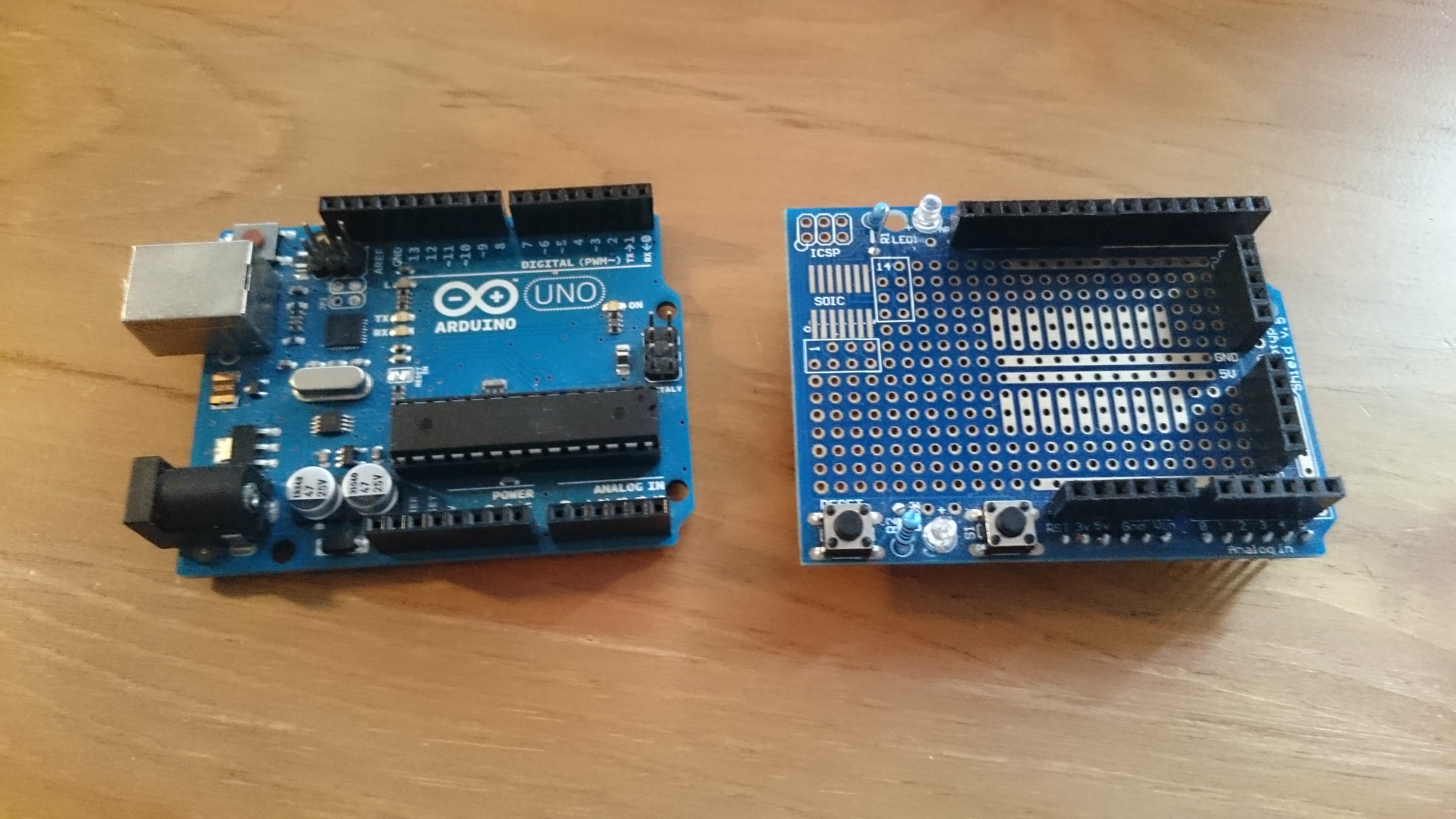
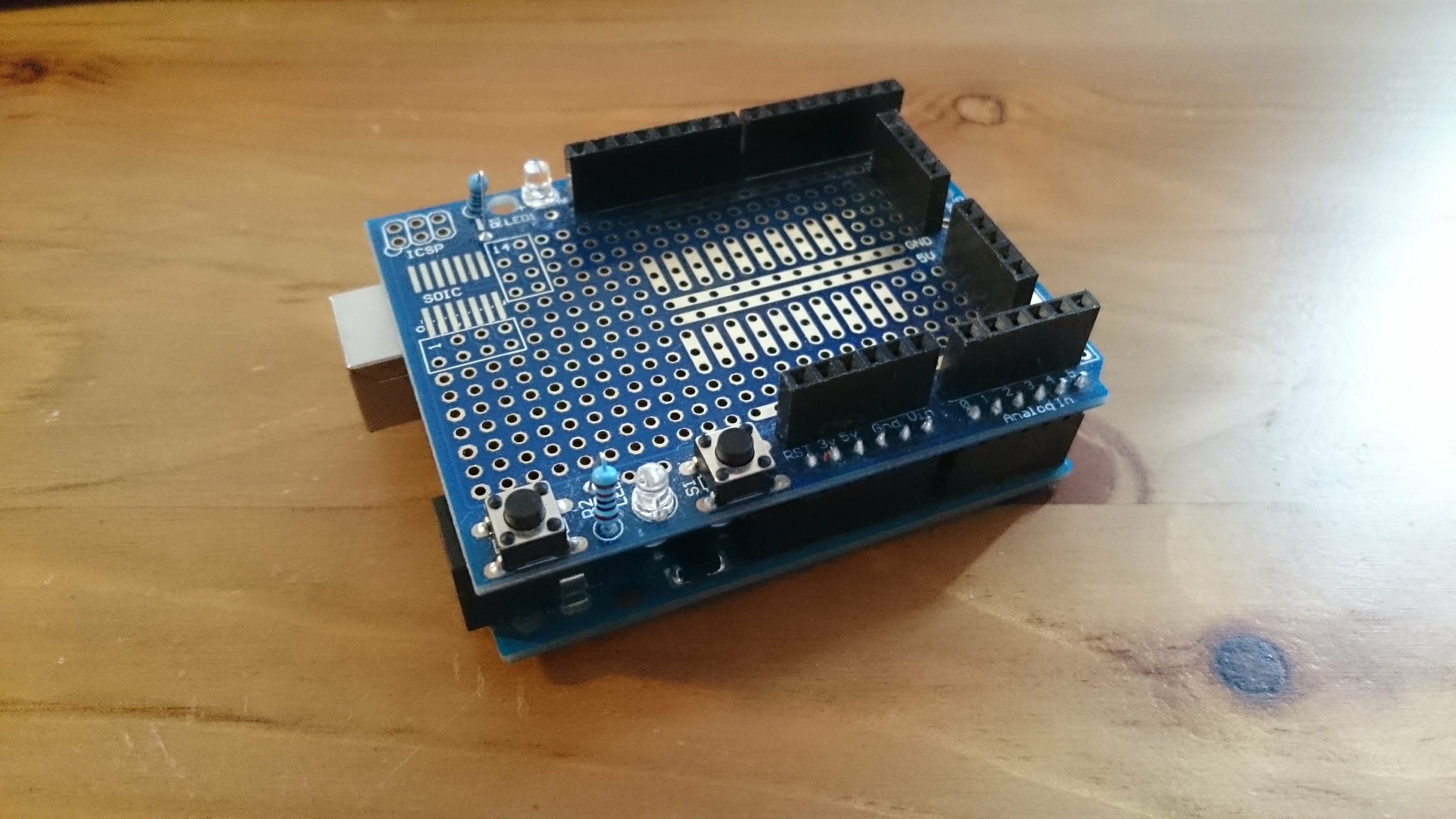
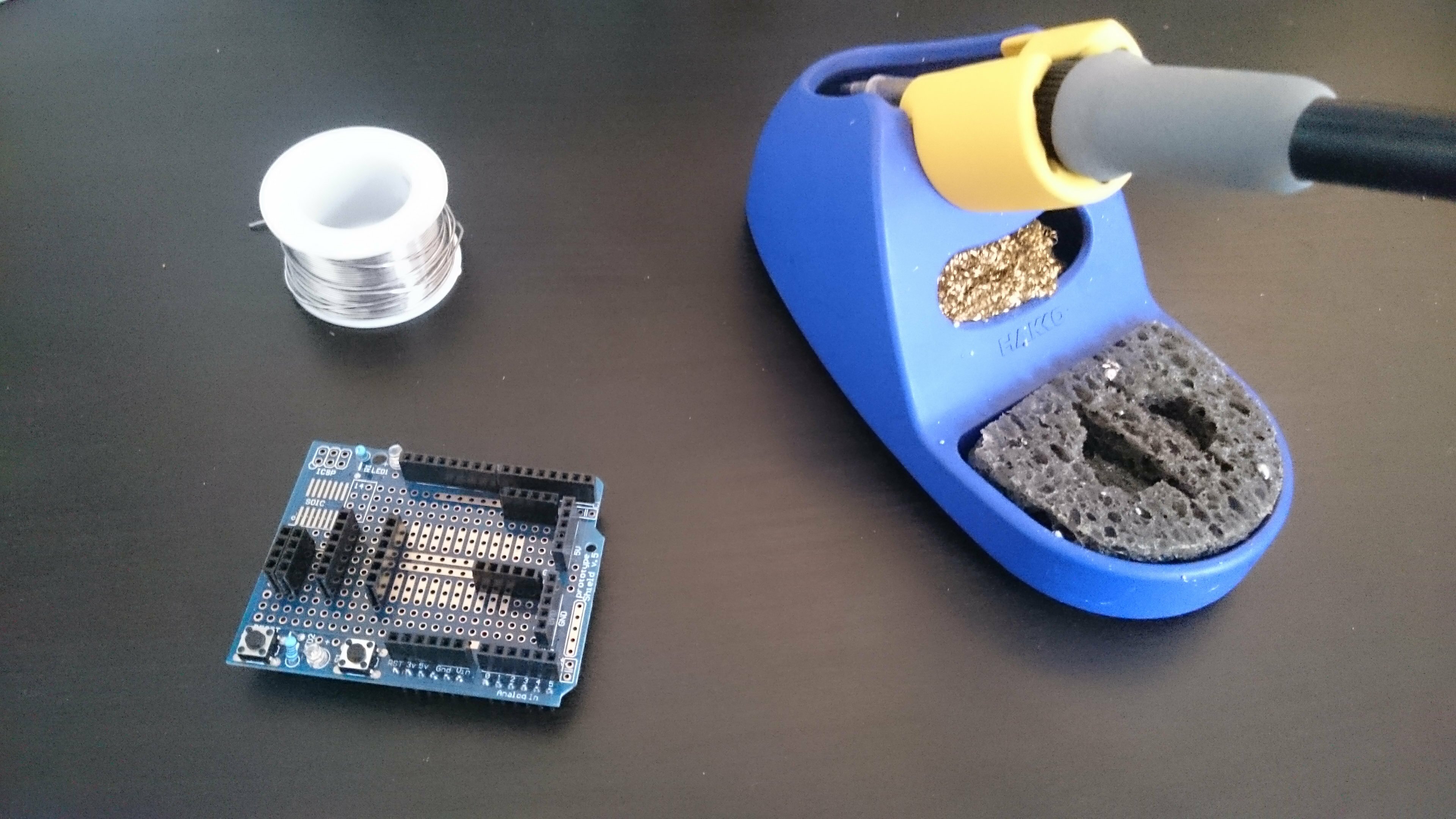
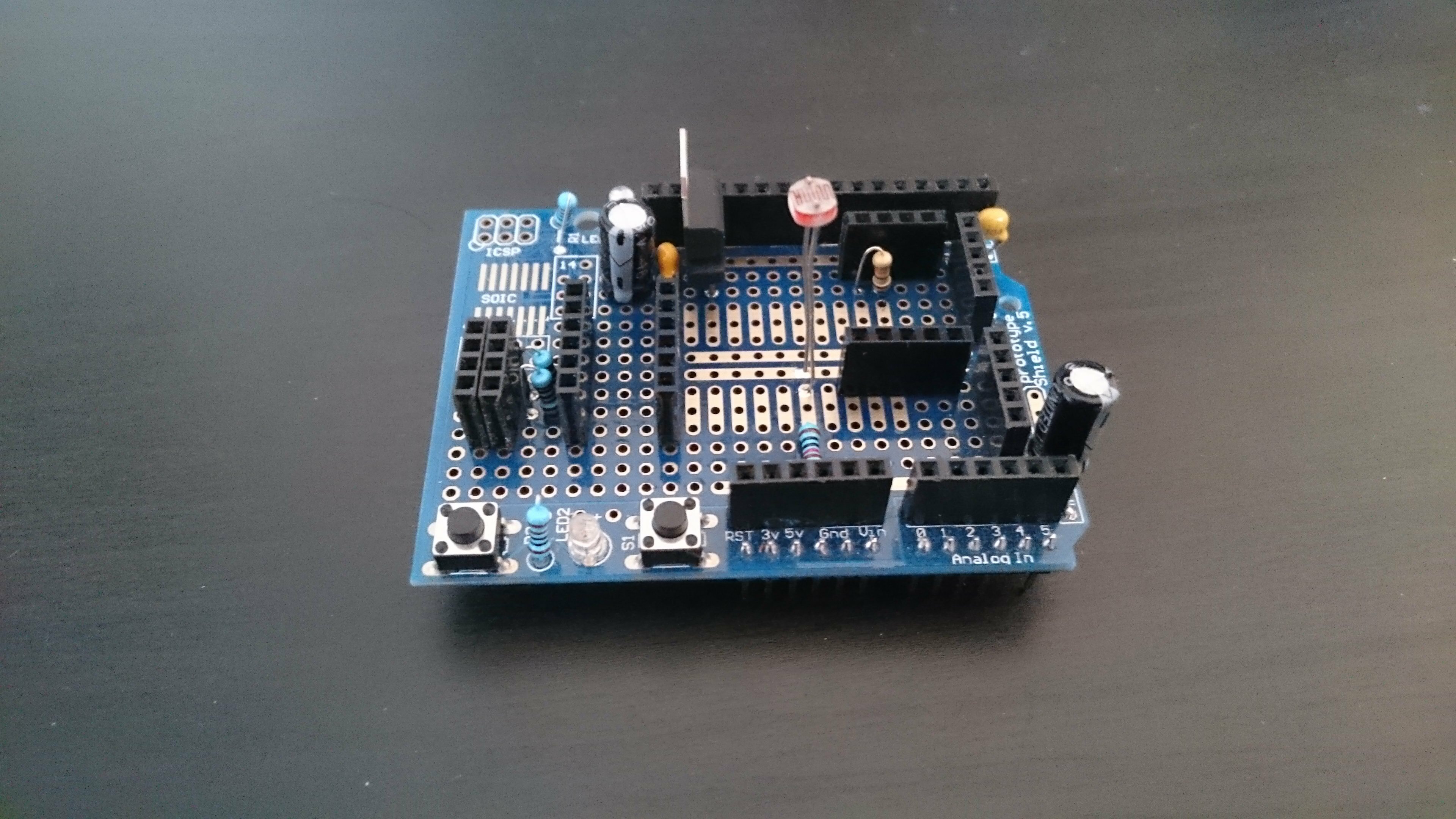
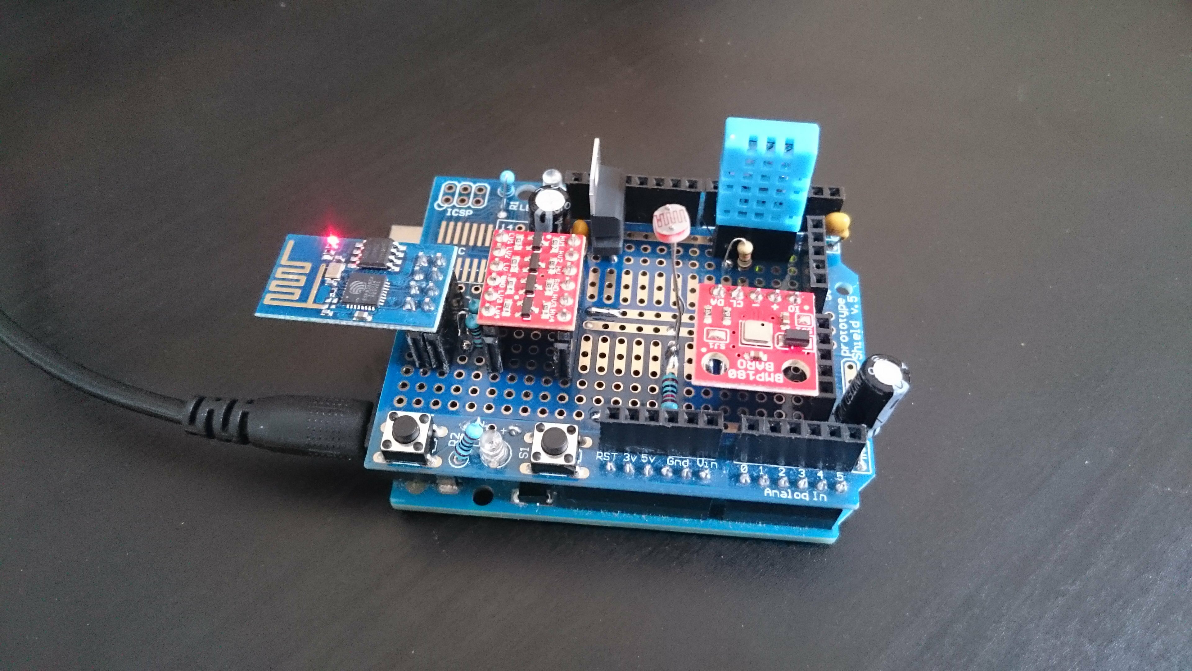
This is a protoshield I got from SainSmart a while ago. As you can see it’s basically a stackable perfboard with a couple of leds and buttons plus headers so that the pins of the Arduino are still accessible.
You won’t necessarily have the exact same layout on your model so the first thing to do is to play a little mind game of Tetris. Try things out, try to imagine the most elegant way to place your components. Think about the connections you will need to make. One word of advice : if you end up using an external power supply plugged to the jack, the current will flow through a voltage regulator located between the crystal and the jack which produces heat to dissipate its power. So you want to keep your sensors as far as possible from the zone above it.
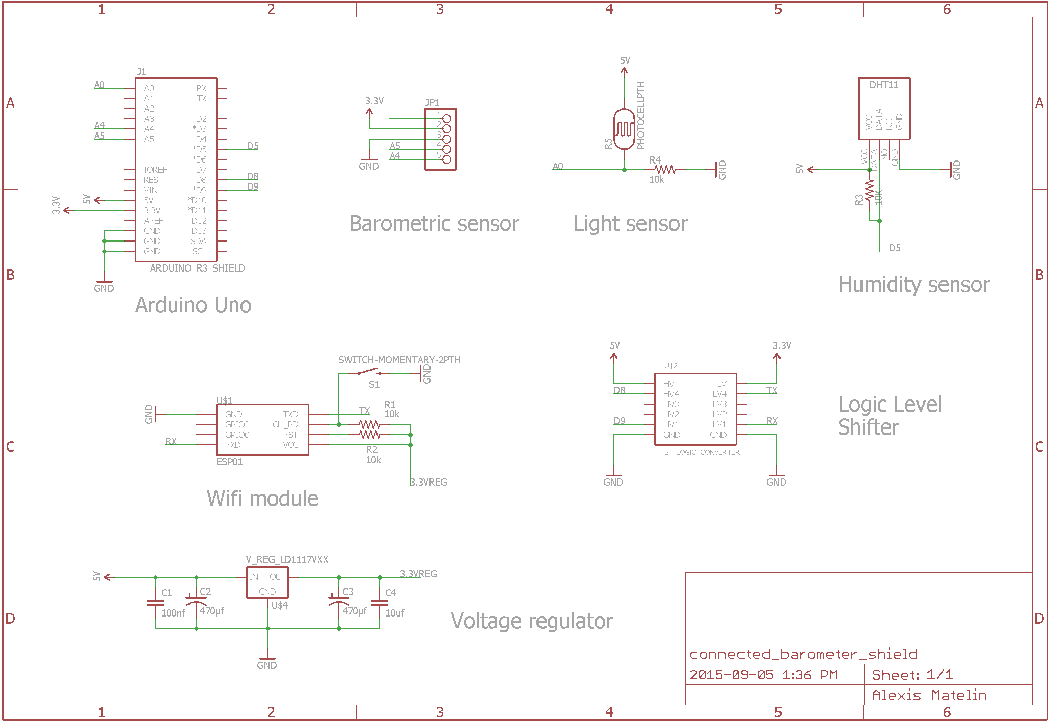
The schematic is the final version of the circuit, where the connections have been adjusted to work well with the shield and minimize the number of wires crossing. The DHT11 is now connected to pin D5 (D7 before), the Serial lines on the Arduino become 8(Rx) and 9(Tx) (2 and 3 before). Coincidentally different pins are used on the level shifter. The pushbutton already present on the shield is used as the reset switch for the ESP.
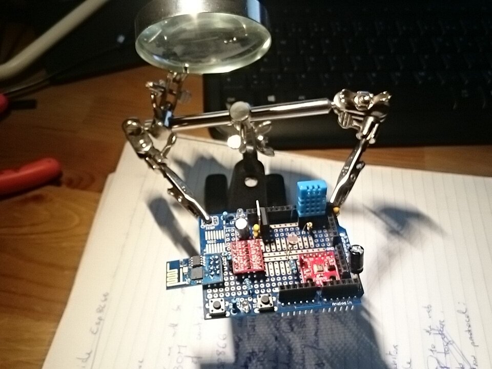
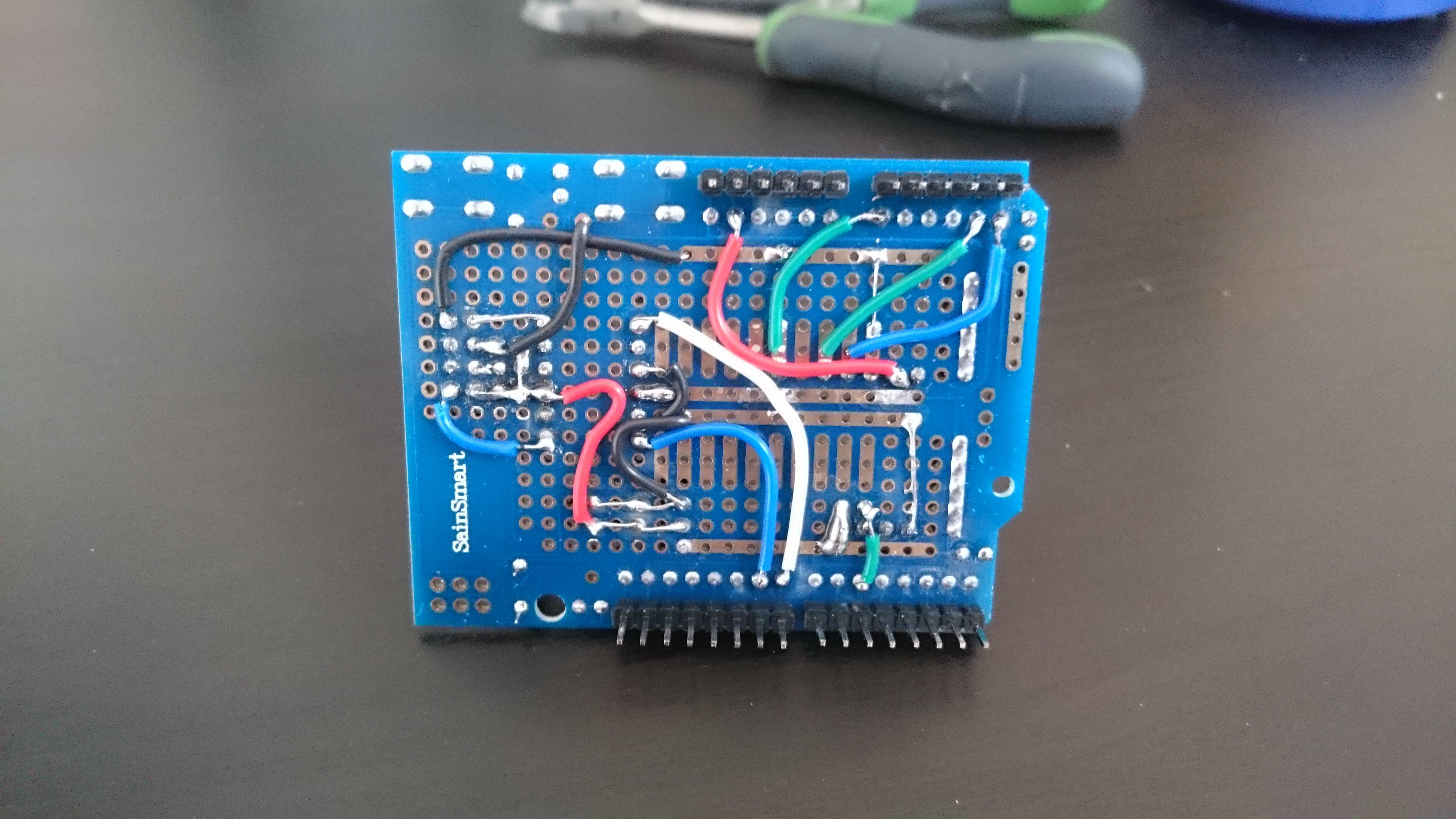
Ready to solder roughly 50 pins ? Well heat your soldering iron and get to it! I don’t know if there is a right way to do this. I chose to start with the headers because they provided a good reference point for the next part, which was soldering in the components. Eventually I made the connections, starting with the ones that only necessitated to join two or several holes together, then finishing with the wires.
Probably take a moment to test your connections with a multimeter, just to ensure that there are no false contact/short circuit anywhere before you plug in anything.
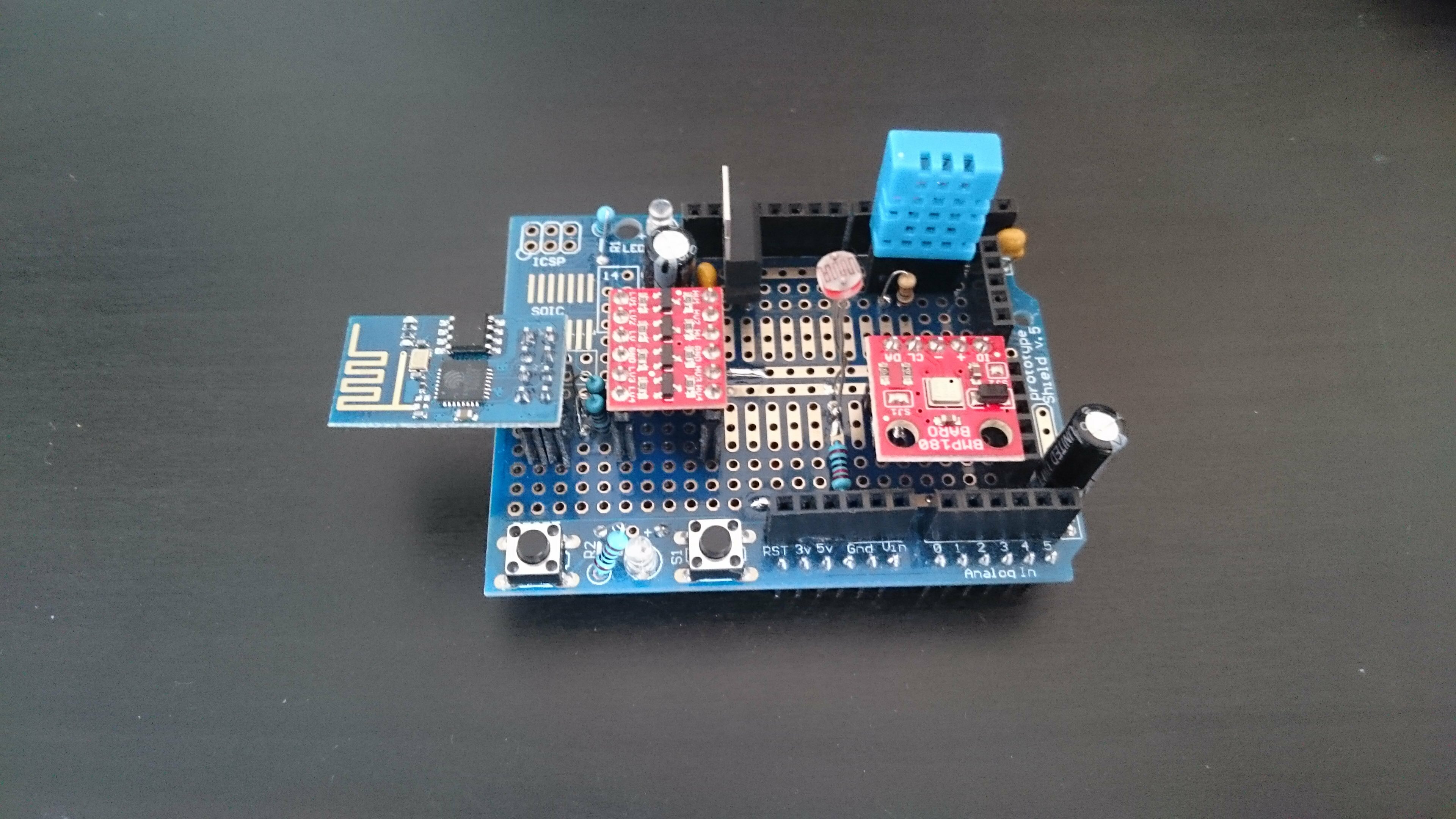
Et voilà ! Add your stackable components and you’ll have a functional (let’s hope so!) connected barometer shield. Neat isn’t it ?
Pushing data online
Thingspeak
We will use their services as an end point for our data. Thingspeak presents itself as “The open data platform for the Internet of Things”. You create a channel to which you send your data. Each data stream is represented as a “Field”. Each field has its own plot on the Channel’s page which can be customized. You can then connect to other services to analyze or act upon your data, but that’s out of the scope of this tutorial.
The service is very easy to use :
- Create a new account. You will be redirected on the Channels page.
- Create a new channel. Provide a name and if you want a description for your channel. Enable as much fields as you need, 4 in our case. If you provide geographical coordinates a google map widget will localize the channel. Choose weather or not to make it public. Finally click Save Channel. You will be redirected to the channel’s private view.
- Click on API Keys and write down the ‘Write API Key’. This is what we need in order to send data to the channel.
- Send the following GET request :
GET /update?key=YOUR_API_KEY&field1=5&field2=10\r\nto the host api.thingspeak.com on port 80. You can simply past this in your browser if you want :http://api.thingspeak.com/update?key=YOUR_API_KEY&field1=5&field2=10. - Watch amazed as the data points magically appear on your plots.
Note :If you’re so impatient to try things out that you don’t want to take a minute to create an account, I made a channel for this purpose.
Address : https://thingspeak.com/channels/54807.
Write API key : 241Q79KE3WNUBT01.
Request : GET /update?key=241Q79KE3WNUBT01&field1=5&field2=10&field3=15\r\n or http://api.thingspeak.com/update?key=241Q79KE3WNUBT01&field1=5&field2=10&field3=15.
Communication protocol
Since the ESP can be unstable at times we want our code to manage potentially unsuspected events. We do that by checking the state of responsiveness of the module before starting any action. The protocol is detailed in the following pseudo-code :
setup()
    esp8266 start Serial coms

    is esp8266 ok ?
        yes :
            is connected to provided SSID ?
                no : connect Wifi (SSID, PASS)
        no : reset esp8266

loop()
    temperature = getTemperature
    humidity = getHumidity
    pressure = getPressure
    luminosity = getLuminosity

    is esp8266 busy ?
        yes :
            do nothing during this loop
        no :
            is connected to provided SSID ?
                yes :
                    send GET request with temperature humidity pressure luminosity to thingspeak
                no :
                    connect Wifi (SSID, PASS)
                    is Wifi connected ?
                        no :
                            reset esp8266

    wait until next loop
Code
You can find the code in the repository of the tutorial in the ‘main’ subdirectory. It is composed of a .ino file which is your usual sketch + an esp8266 class which I handcrafted to match my needs. It’s pretty much still a draft so I will try to improve it in the future. But it works.
Line 33 you can set the parameter debug to true. It will print messages to the hardware Serial informing you of the status of the ESP.
There are other esp8266 arduino libraries out there but I could never get them to work. You’re very welcome to try and to give me some feedback on that because I’m not a big fan of reinventing the wheel.
You should now see the data points from your sensors populating your plots! Congratulations!
What will you do next ? Add different sensors ? Use the data to make an intelligent domotic system ? Tell me in the comments !
Post scriptum
If I had to do it again, I’m not sure that I would put the DHT11 on this header. It has a tendency to provoke false contacts between the pins and their socket. I’d also like to drop the arduino and create a standalone PCB where the ESP8266 is the sole micro-controller.
I mentioned the heat problem. On way to solve it is to power the board from the USB connected to a cell-phone wall charger where the current rating is as close as possible as the one from a USB port (500mA). Thus the voltage regulator is bypassed.
Finally : I initially wanted to use Plotly instead of Thingspeak because I really like their plots and the fact that they have clients in so many languages. But I could not figure out the right request. If you’d like to help me with that, I asked a question about it on stackoverflow.
Sources
- On the ESP8266 :
- The ESP8266 Community forum.
- A very complete list of ressources (examples, libraries, forums etc.).
- Internet of Home Things: a blog with a lot of interesting articles involving the ESP.
- “noob’s guide to ESP8266 with Arduino Mega 2560 or Uno”.
- Program the ESP8266 using arduino IDE.
- Esp8266 Wiki.
- Kolban’s book on the ESP8266 (regularly updated).
- ESP8266: Reflash Dance!
- On the sensors :
- The DHT11 Arduino library.
- Sparkfun’s BMP180 Arduino library.
- Adafruit’s BMP085 Arduino library (compatible with the BMP180).
- A comparison of different humidity and temperature sensors.
- Miscellaneous :
- The frizting diagrams of this tutorial.
- The Eagle schematic.
- The additional libraries I had to use for the diagrams/schematic.
Thank you for making this 🙂 I’ve been looking for this same thing, and Now I feel like I can finally learn something. I can’t wait for all my parts to get here.
I’m glad that it was of some use to you. Don’t hesitate to contact me if you have any question once you get your parts!
Thanks for the effort you’ve expended in documenting this.
Now please look up the definitions of ‘loose’ and ‘lose’.
-Right after deleting this comment. Your post shouldn’t be diminished by a spelling nazi.
It’s quite easy to let a spelling error slide between 3000 words, which doesn’t mean that I don’t know the definition of the word (even though English is not my native language).
It’s also quite easy to be cynical about it 😉
But I’m always in favor of improvement so thank you for spotting it.
Alexis,
Thank you for such a detailed article on ESP8266.
I am now much more educated about this piece of hardware.
I got a couple of the ESP12-E version which have some GPIO’s that probably might eliminate the need of the Arduino, reducing the cost, size, etc even more…
Thanks
It feels great to read that my articles can be useful. Don’t hesitate to drop me a line about your experience with the ESP12, it seems to be more stable the the ESP01. Plus you’re right, with the additional pins, who needs an Arduino !
Thanks. U have explained things the way no one has explained before. Same problem happened to me. I was about to give up the idea of using esp8266 in my project. Now I think I can give it a try. I am only using arduino uno along with esp8266 module.And I don’t want to spend money on buying that FTDI board. My project is to send data from AD8232 single lead heart rate monitor To any convenient server to plot a real time Ecg curve that can be seen from any part of the world. I know very well how to connect esp8266 with Arduino Uno but things didn’t work out well. I am sure I can put it to work. But I m not sure how to connect Arduino uno + esp8266+ AD8232 and what the code will be to upload to arduino. I think U can help me out with this. Thanks again.
Thank you! Very useful guide!
I tried the logic level shifter instructions but my ESP8266 is not responding…
ESP8266 is working with FTDI. I also set the baud rate to 9600 (from 115200) with AT+UART_DEF=9600,8,1,0,0 but still it is not responding. How can I debug it?